
Full-bridge phase-shift converter with auxiliary zero-voltage-switching circuit

a phase shift converter and zero-voltage switching technology, applied in the direction of dc-dc conversion, power conversion systems, instruments, etc., can solve the problems of large heat loss, increase in switching losses of turning on and turning off power switching elements, and elimination of linear power supply

Inactive Publication Date: 2011-11-10
CHICONY POWER TECH CO LTD
View PDF2 Cites 47 Cited by
  • Summary
  • Abstract
  • Description
  • Claims
  • Application Information

AI Technical Summary

Benefits of technology

[0024]Therefore, the auxiliary inductor of the auxiliary zero-voltage-switching circuit is used to reinforce sufficient inductive energy on the leading-edge leg, thus achieving normally zero-voltage-switching operations of the full-bridge phase-shift converter.

Problems solved by technology

The traditional linear power supply has cumbersome isolated transformers and heat sinks therein, thus the linear power supply has already been eliminated gradually due to low efficiency.
When the operation frequency increases, therefore, the switching losses of turning on and turning off the power switching elements will increase with frequency.
However, this will result in large heat losses to reduce efficiency and lifetime of the switching power supply.
In addition, the heat dissipating apparatus is needed to install, while volume and costs increase.
More particularly, non-ideal effect of switching the power switching elements causes problems of higher voltage and current stress as well as electromagnetic interference.
However, the ZCS is achieved to cause switching losses due to electric charges stored in the power switching elements.
Accordingly, the full-bridge phase-shift ZVS converter is not suitable for large varying load conditions.

Method used


Image

  • Full-bridge phase-shift converter with auxiliary zero-voltage-switching circuit
  • Full-bridge phase-shift converter with auxiliary zero-voltage-switching circuit
  • Full-bridge phase-shift converter with auxiliary zero-voltage-switching circuit

Examples


Embodiment Construction

[0032]Reference will now be made to the drawing figures to describe the present invention in detail.

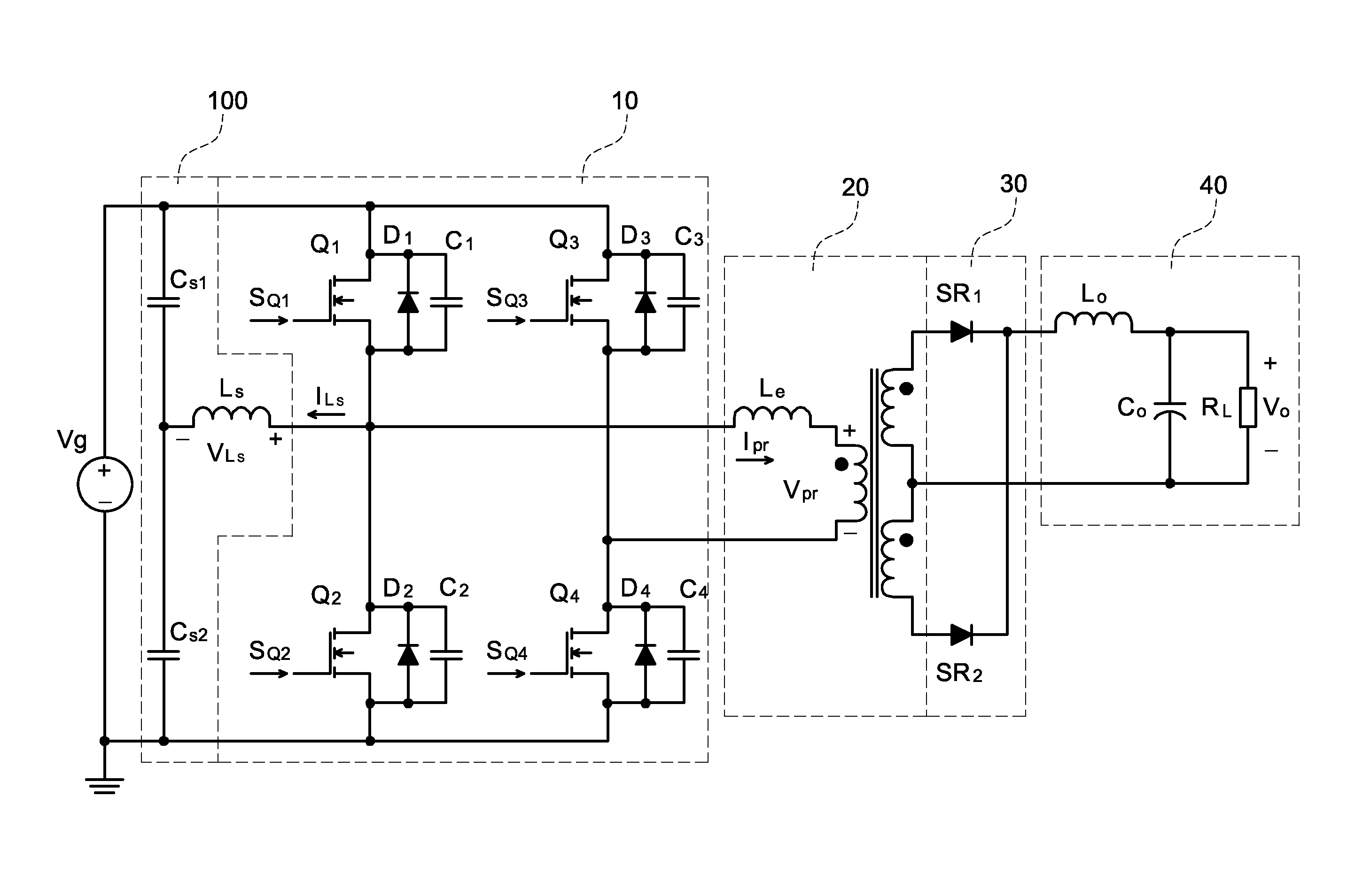
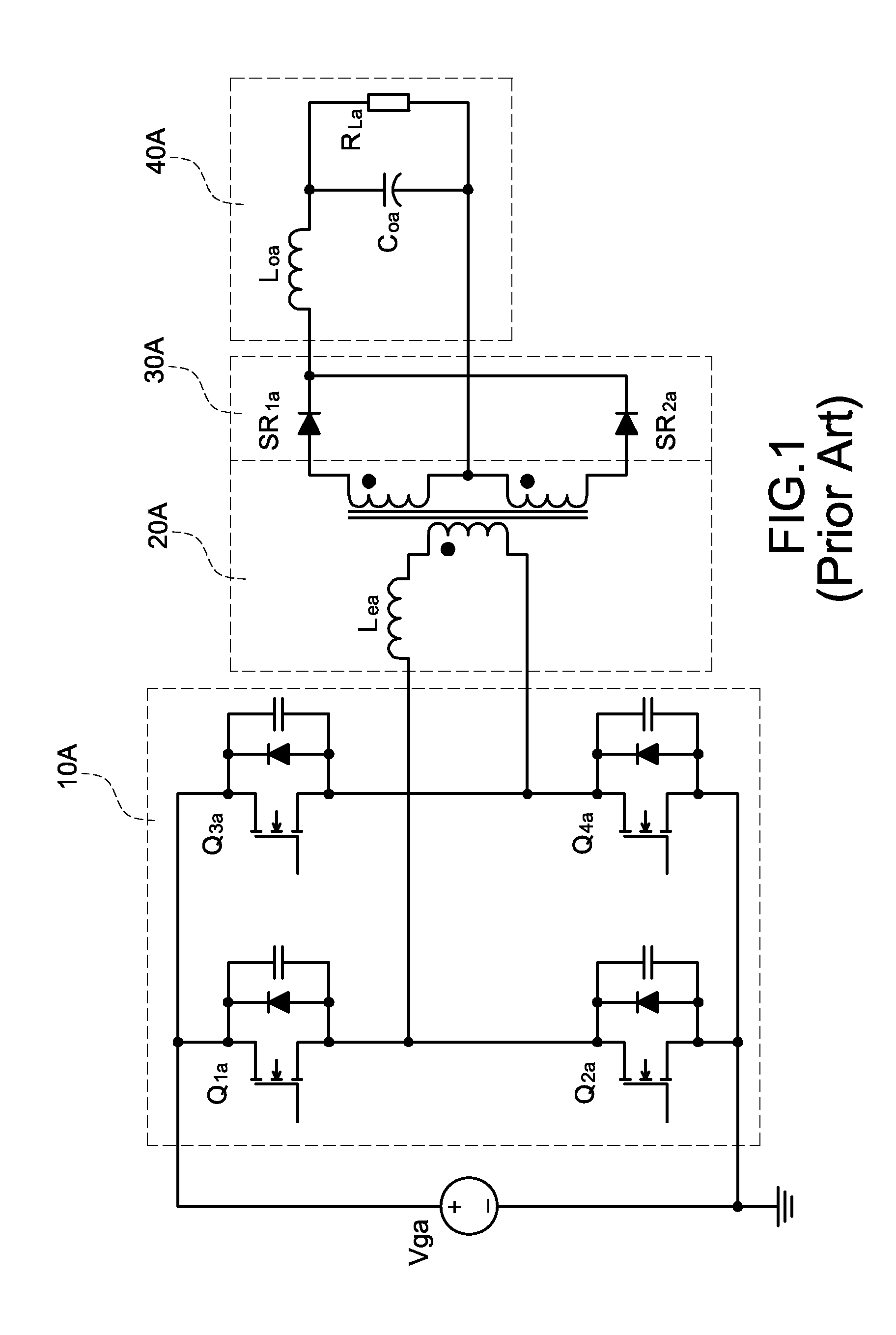
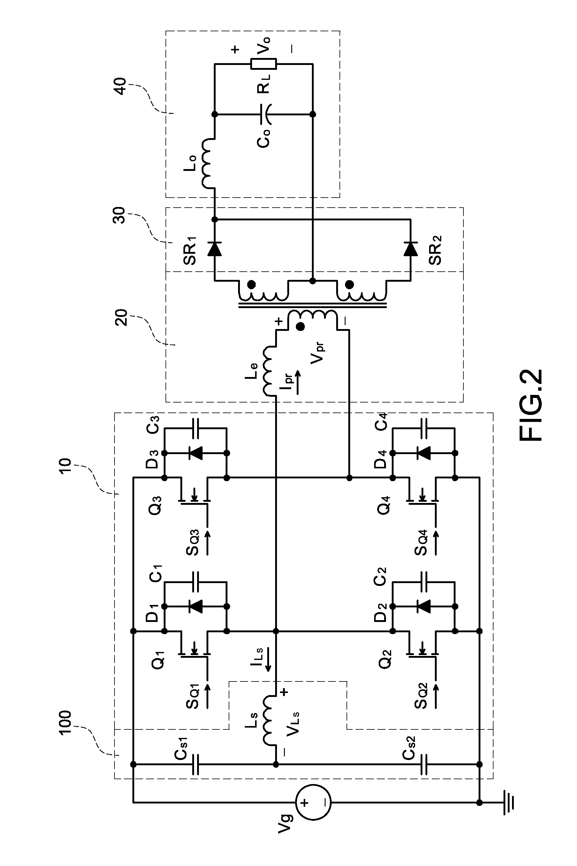
[0033]Reference is made to FIG. 2 which is a full-bridge phase-shift converter with an auxiliary ZVS circuit according to the present invention. The full-bridge phase-shift converter is electrically connected to a DC input voltage Vg to transmit energy provided from the DC input voltage Vg to a connected load RL. The full-bridge phase-shift converter mainly includes a full-bridge switching circuit 10, an isolated transformer 20, a full-wave rectifying circuit 30, and a low-pass filtering circuit 40. The significant difference between the prior art full-bridge phase-shift ZVS converter and the present invention is that the latter further includes an auxiliary zero-voltage-switching circuit 100.

[0034]The full-bridge switching circuit 10 has four power switching elements, namely, a first power switching element Q1, a second power switching element Q2, a third power switching element Q3, ...


PUM


Abstract

A full-bridge phase-shift converter with an auxiliary zero-voltage-switching circuit includes a full-bridge switching circuit, an isolated transformer, an auxiliary zero-voltage-switching (ZVS) circuit, a full-wave rectifying circuit, and a low-pass filtering circuit. The full-bridge phase-shift converter is used to send energy which is supplied from a DC input voltage to a load. Therefore, an auxiliary inductor of the auxiliary ZVS circuit is provided to reinforce sufficient inductive energy on a leading-edge leg, thus achieving normally zero-voltage-switching operations of the full-bridge phase-shift converter.

Description

BACKGROUND OF THE INVENTION[0001]1. Field of the Invention[0002]The present invention relates to a full-bridge phase-shift converter, and more particularly to a full-bridge phase-shift converter with an auxiliary zero-voltage-switching circuit.[0003]2. Description of Prior Art[0004]With the development of power semiconductor technology, many electronic produces are now light, thin, short, and small, and this trend will continue. The traditional linear power supply has cumbersome isolated transformers and heat sinks therein, thus the linear power supply has already been eliminated gradually due to low efficiency. Instead of the linear power supply, the switching power supply is used for high-frequency operations. The switching power supply has a lot of advantages, including smaller volume, lighter weight, and higher efficiency.[0005]In general, the switching power supply adopts a traditional hard switching technology. When the operation frequency increases, therefore, the switching l...

Claims


Application Information

Patent Timeline
IPC IPC(8): H02M3/335
CPCH02M3/3376
Inventor CHRISTOPHER, CHEUNG-TAK SIT
Owner CHICONY POWER TECH CO LTD
Learn More