Computed tomography system

a tomography system and computed tomography technology, applied in tomography, instruments, applications, etc., can solve the problems of high overall body dose to which the patient is exposed, and achieve the effect of low x-ray exposure, good image quality, and versatile structur

Inactive Publication Date: 2011-11-10
SIEMENS AG
View PDF9 Cites 24 Cited by
  • Summary
  • Abstract
  • Description
  • Claims
  • Application Information

AI Technical Summary

Benefits of technology

[0005]The object of the present invention is to provide a computed tomography system that ensures particularly good image quality with the lowest possible x-ray exposure and a versatile structure.
[0007]The inventive computed tomography system, featuring an annular CT gantry with a central opening, a recording system that can be rotated within the gantry having an x-ray source and an x-ray detector apparatus, it being possible to remove a part of the ring of the CT gantry from the ring at least partially so that there is a break in the ring, through which an examination object can be moved into the central opening, the computed tomography system being configured for phase contrast x-ray imaging, offers a particularly good image quality in particular for soft tissue representation with a relatively low x-ray dose for an examination object. This allows more precise diagnoses to be made and patient exposure is low. The break in the gantry allows the computed tomography system to be used in a particularly flexible manner, since for example it is particularly easy to position the examination object and the examination object or patient can be accessed particularly easily by a physician.
[0014]According to a further embodiment of the invention the x-ray source features a plurality of field emission x-ray sources for emitting quasi-coherent x-ray radiation. Integrating an x-ray emitter with field emission x-ray sources means that there is no need for the complex source grating to produce monochromatic x-ray radiation, since the field emission x-ray sources are a simple and outlay-free option for producing quasi-coherent x-rays with a narrow focus. This allows the CT to be produced in a particularly compact and low-cost manner.
[0016]With a field emission x-ray source or the associated field emission cathode electrons are emitted by applying a sufficiently large electric field. Field emission is achieved for example by a simple diode mode, in which a prevoltage is applied between anode and cathode. Electrons are emitted by the cathode when the electric field exceeds the threshold for emission. A triode construction can also be provided, in which a gate electrode is disposed close to the cathode. Electrons are emitted here by applying a prevoltage between gate and cathode. The emitted electrons are then accelerated by a high voltage between gate and anode. Field emission cathodes allow a very high, easily controlled and easily focused electron beam stream. Generally the field emission emitter and the field emission x-ray sources mean that the invention has the advantages of low heat generation at the x-ray source and a low weight, both due to the field emission emitter itself and also due to the lack of need for or reduction of a cooling system. Such a field emission emitter also has a high level of compactness compared with conventional x-ray emitters, with the result that a high-quality, flat x-ray source with a surface of many adjacently disposed focal points is possible for the first time. This is ensured in particular by an array with a plurality of field emission emitters. Also the service life of field emission emitters is much longer than that of known x-ray emitters with thermal cathodes. Also a field emission cathode can be started up quickly without heating unlike a thermal cathode. Additionally the easily focused electron stream means that a higher spatial resolution can be achieved for x-ray imaging.
[0019]According to a further embodiment of the invention the gantry features at least two recording systems, each with one x-ray source and one x-ray detector apparatus. In a CT with two recording systems the first recording system can advantageously be configured for phase contrast x-ray imaging and the second recording system for fluoroscopy x-ray imaging. This allows the CT both to provide conventional recordings and also to supply particularly high-quality soft tissue representations, making it also suitable for minimally invasive interventions and minimally surgical treatments.
[0020]Advantageously for particularly efficient, fast and simple spatial adjustment the CT gantry is disposed in a pivotable manner on a mount, in particular a ceiling mount.

Problems solved by technology

One disadvantage of computed tomography is the high overall body dose to which the patient is exposed.

Method used


Image

  • Computed tomography system
  • Computed tomography system
  • Computed tomography system

Examples


Embodiment Construction

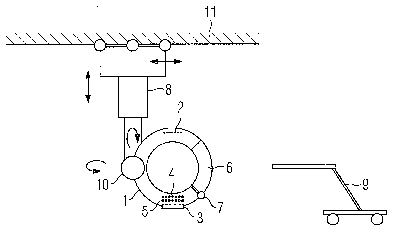
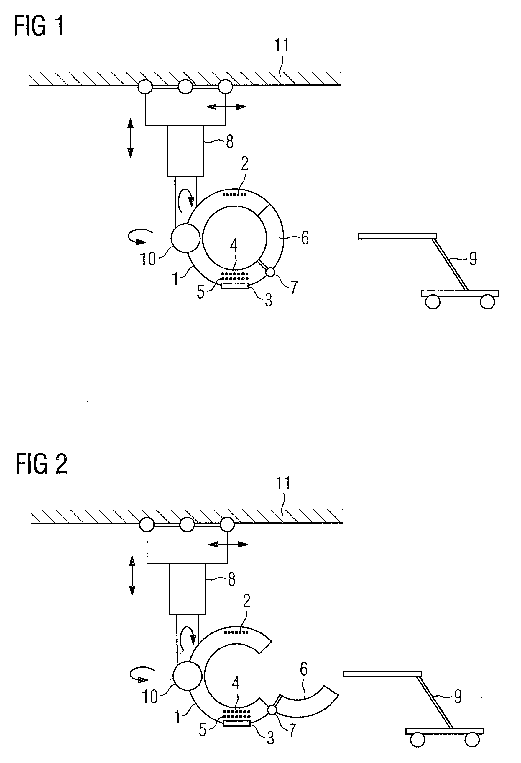
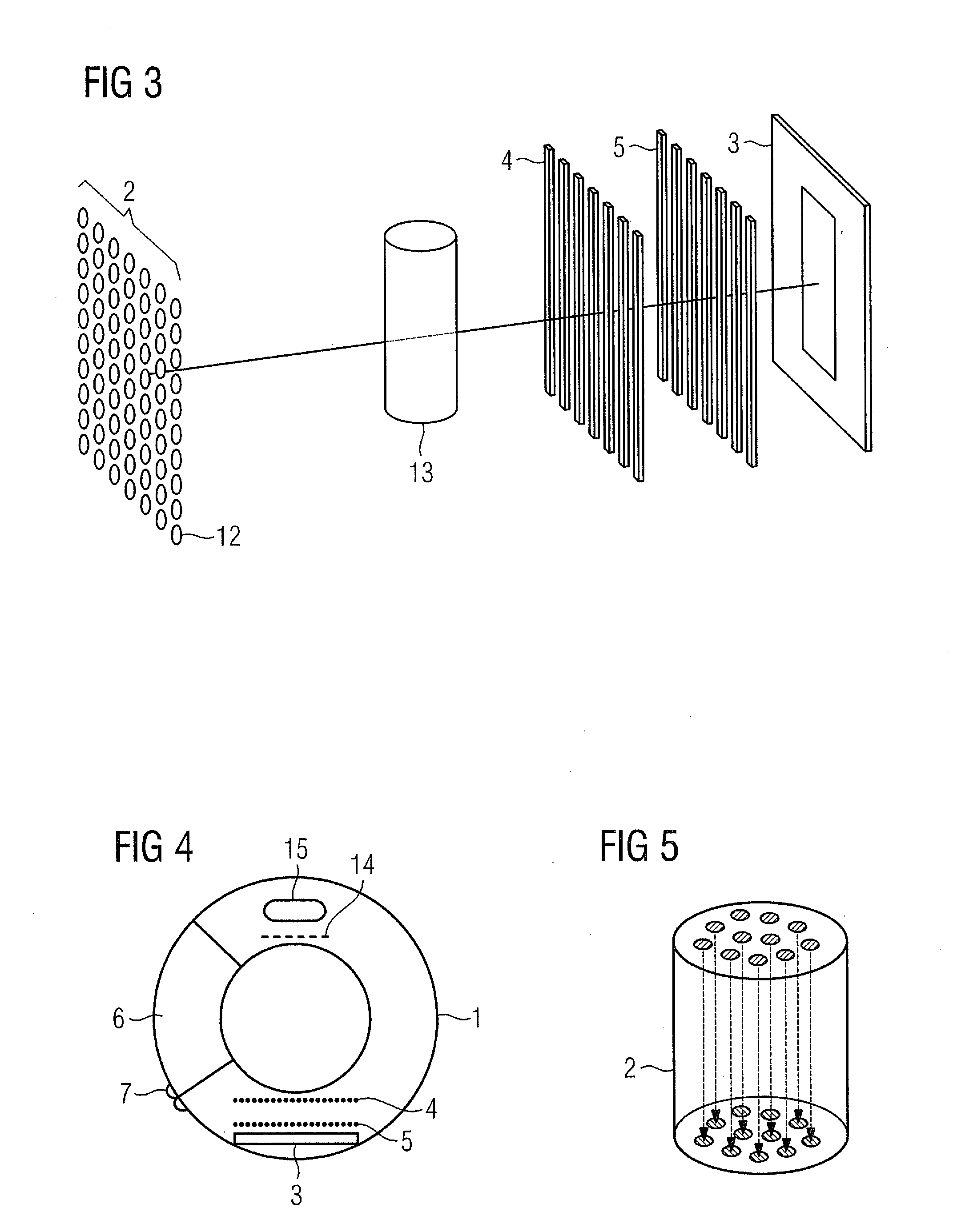
[0031]FIG. 1 shows an inventive computed tomography system with a CT gantry 1, the CT gantry 1 having a ring segment 6, the position of which can be changed relative to the remainder of the gantry. The gantry 1 is configured as annular and features a central opening 17 in which an examination object can be positioned. The gantry 1 also features a hollow space in the interior of the ring, in which a recording system is disposed in such a manner that x-ray images can be recorded of the examination object disposed in the opening. The recording system can rotate about the opening (through 360°) within the hollow space and can record x-ray images as it rotates. The recording system is configured for phase contrast x-ray imaging and in addition to an x-ray source in the form of a field emission emitter 2 and an x-ray detector apparatus 3 it also features a phase grating 4 and an amplitude grating 5. The field emission emitter 2 features a plurality of field emission x-ray sources 12, e.g....


PUM


Abstract

A computed tomography system is provided for allowing it to be deployed more effectively. The computed tomography system features an annular CT gantry with a central opening, a recording system that can be rotated within the gantry. The recording system has an x-ray source and an x-ray detector apparatus. It is possible to remove a part of the ring of the CT gantry from the ring at least partially so that there is a break in the ring, through which an examination object can be moved into the central opening. The computed tomography system is for phase contrast x-ray imaging.

Description

CROSS REFERENCE TO RELATED APPLICATIONS[0001]This application claims priority of German application No. 10 2010 019 991.5 filed May 10, 2010, which is incorporated by reference herein in its entirety.FIELD OF THE INVENTION[0002]The invention relates to a computed tomography system.BACKGROUND OF THE INVENTION[0003]Projection x-ray recording is one of the medical examinations used most frequently for imaging purposes. Typical recordings include thoracic recordings and pelvic recordings on a standing patient, cranial recordings, recordings of the arms or legs to ascertain a break in such limbs for example. In this process an x-ray source emits x-ray beams onto an examination object; these penetrate the examination object, some of them being reflected or absorbed in the tissue, producing an x-ray image on an x-ray detector located behind the examination object. A vacuum tube is used here to produce ionizing radiation. The x-ray image produced is based on the differing rates of absorptio...

Claims


Application Information

Patent Timeline
Patent Type & Authority Applications(United States)
IPC IPC(8): A61B6/03B82Y5/00
CPCA61B6/035A61B6/4035A61B6/4291A61B6/4021A61B6/484A61B6/505G21K2207/005A61B6/4464
Inventor MASCHKE, MICHAEL
Owner SIEMENS AG
Why Eureka
Try Eureka