Injection needle assembly and drug injection device

a technology of injection needle and needle tube, which is applied in the direction of intravenous devices, etc., can solve the problems that the tip end of the needle tube may reach the subcutaneous tissue and cannot achieve the expected effects, and achieve the effect of constant height of the raised portion of the skin formed by the skin deformer

Active Publication Date: 2011-11-10
TERUMO KK
View PDF9 Cites 32 Cited by
  • Summary
  • Abstract
  • Description
  • Claims
  • Application Information

AI Technical Summary

Benefits of technology

[0024]With the injection needle assembly and the drug injection device according to the present invention, due to the provision of the guide portion for guiding the pressing parameter when puncturing the living body, the needle tip and the blade face of the needle tube can be securely positioned in the upper layer of skin.
[0025]With the injection needle assembly and the drug injection device according to the present invention, the height of the raised portion of the skin formed by the skin deformer can be made constant, and the needle tip and the blade face of the needle tube can be securely positioned in the upper layer of skin.
[0026]Further, with the injection needle assembly and the drug injection device according to the present invention, the pressing force applied from the needle tube and the stabilizer to the living body can be guided to the user by the guide portion, and therefore the user can stick the needle tube into the skin with ensuring a suitable predetermined pressing force. Further, since being able to recognize the suitable pressing force applied from the needle tube and the stabilizer to the living body, the user can use the drug injection device without uneasy feeling, and the needle tip and the blade face of the needle tube can be securely positioned in the upper layer of skin.

Problems solved by technology

Consequently, if the skin is raised in the space between the limiter and the circumference of the needle tube, there is a concern that the tip end of the needle tube may reach the subcutaneous tissue.
Since the epidermis and dermis are composed of dense fibrillar connective tissue and are harder than the subcutaneous tissue, if the tip end of a needle tube reaches the subcutaneous tissue, the administered drug such as vaccine or the like will move from the dermis tissue to the subcutaneous tissue, and therefore the expected effects cannot be obtained.

Method used


Image

  • Injection needle assembly and drug injection device
  • Injection needle assembly and drug injection device
  • Injection needle assembly and drug injection device

Examples


first embodiment

1. First Embodiment

[Configuration Examples of Injection Needle Assembly and Drug Injection Device]

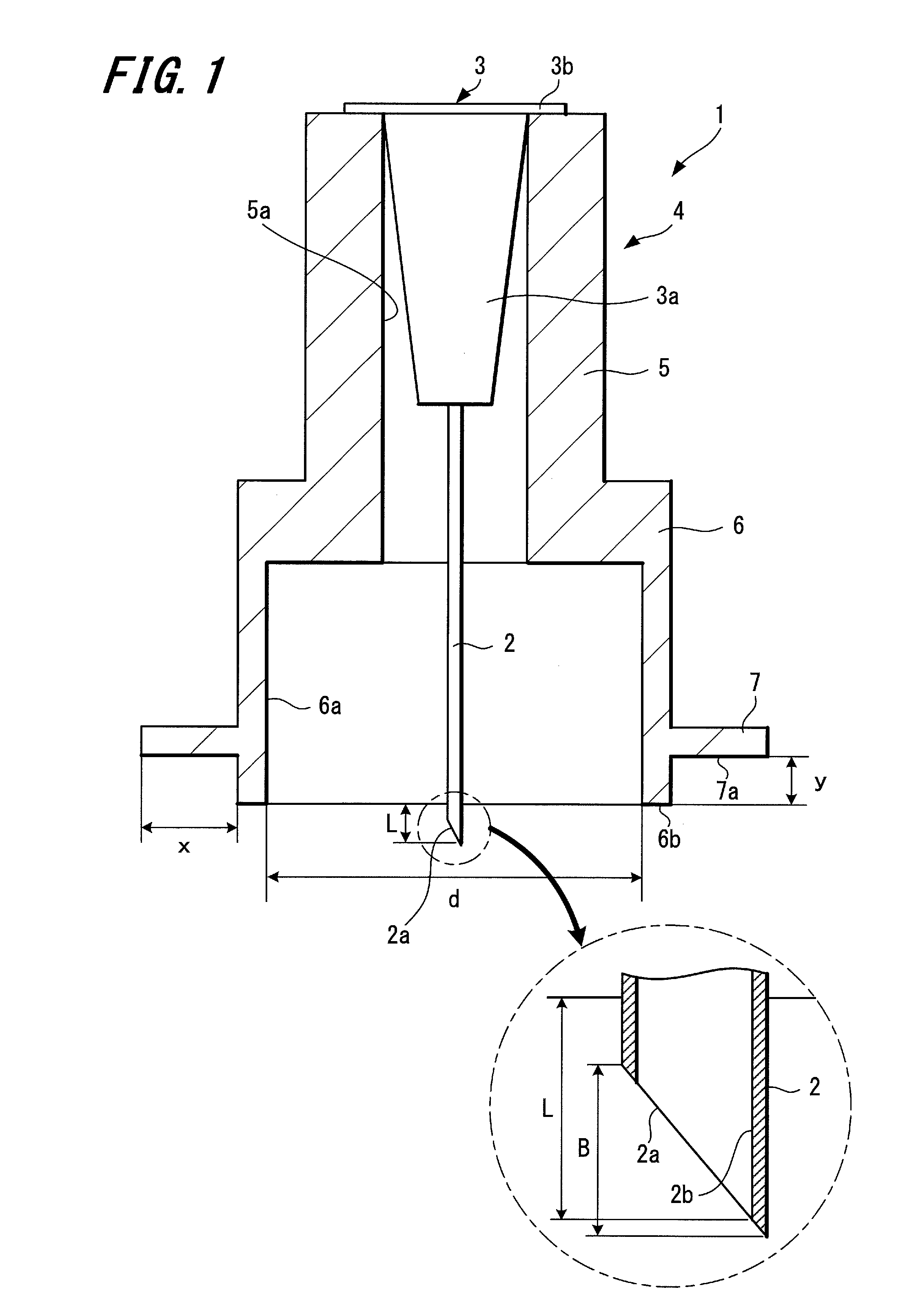
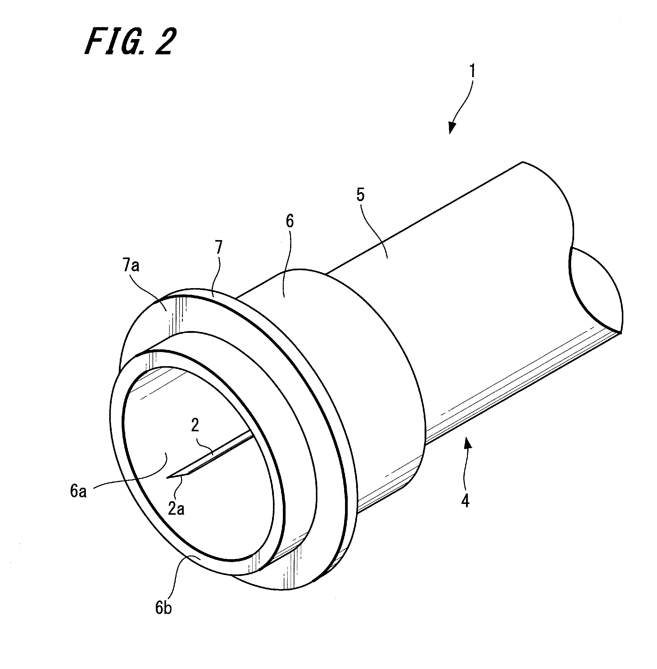
[0046]An injection needle assembly and a drug injection device according to a first embodiment of the present invention will be described below with reference to FIGS. 1 to 3.

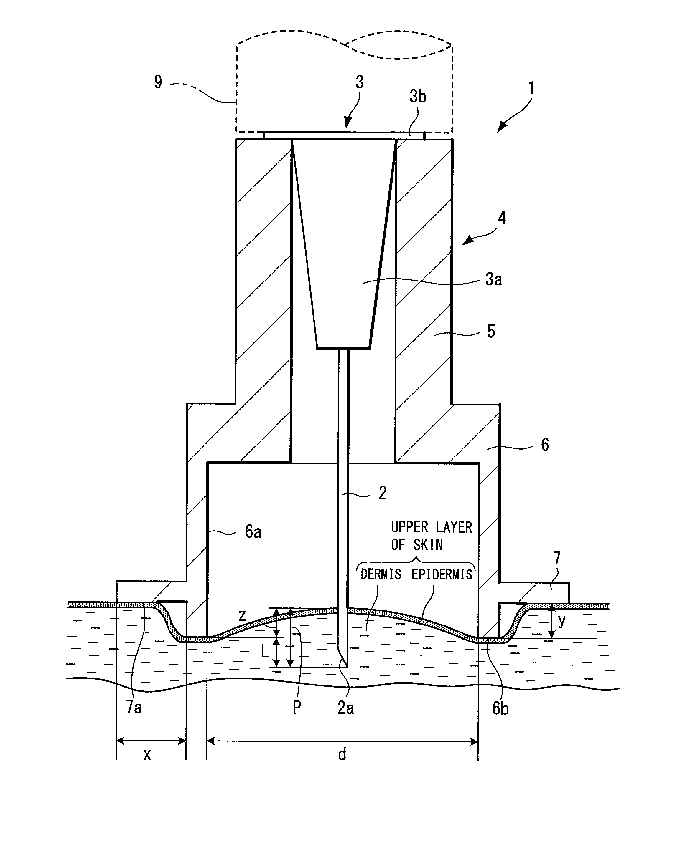
[0047]FIG. 1 is a view showing the configuration of the injection needle assembly according to the first embodiment of the present invention. FIG. 2 is a perspective view showing the injection needle assembly according to the first embodiment of the present invention. FIG. 3 is a view for explaining a state in which a needle tube of the injection needle assembly of the drug injection device is stuck into the skin.

[0048]An injection needle assembly 1 includes a hollow needle tube 2 having a needle hole 2b, a hub 3 which holds the needle tube 2, and a stabilizer (which is a skin deformer) 4 fixed to the hub 3. A drug injection device of the present invention is configured by connecting a syringe 9 (see FIG. 3) with t...

second embodiment

2. Second Embodiment

[Configuration Examples of Injection Needle Assembly and Drug Injection Device]

[0103]An injection needle assembly and a drug injection device according to a second embodiment of the present invention will be described below with reference to FIG. 10.

[0104]FIG. 10 is a view showing the configuration of the injection needle assembly according to the second embodiment of the present invention.

[0105]An injection needle assembly 11 has the same configuration as that of the injection needle assembly 1 of the first embodiment except for a stabilizer 14 and a guide portion 17. Thus, in the second embodiment, the description is made for the stabilizer 14 and the guide portion 17 only, and common components are denoted by common numerals as of the injection needle assembly 1 and the explanation thereof will be omitted.

[0106]Incidentally, the drug injection device of the present invention is formed by connecting a syringe 9 (see FIG. 3) with a hub 3 of the injection needle ...

third embodiment

3. Third Embodiment

[Configuration Examples of Injection Needle Assembly and Drug Injection Device]

[0115]An injection needle assembly and a drug injection device according to a third embodiment of the present invention will be described below with reference to FIG. 11.

[0116]FIG. 11 is a perspective view showing the injection needle assembly according to the third embodiment of the present invention.

[0117]An injection needle assembly 21 has the same configuration as that of the injection needle assembly 1 of the first embodiment except for a guide portion (as the distance recognizer) 27. Thus, in the third embodiment, the description is made for the stabilizer 27 only, and common components are denoted by common numerals as of the injection needle assembly 1 and the explanation thereof will be omitted.

[0118]Incidentally, the injection needle assembly 21 has a hub 3 (see FIG. 1) identical to that provided in the first embodiment. Further, the drug injection device of the present invent...


PUM


Abstract

To securely position a needle tip and a blade face of a needle tube inserted into the skin in a predetermined site of a living body, such as the upper layer of skin, an injection needle assembly includes a needle tube having a needle tip capable of puncturing a living body, a hub holding the needle tube, a stabilizer, and a guide portion. The stabilizer is formed in a tubular shape surrounding the circumference of the needle tube, and an end face is pressed against the skin, and thereby a raised portion of the skin is formed in a tube hole. The guide portion is arranged on the stabilizer, and is adapted to recognize a press-in distance y of the stabilizer to the skin.

Description

TECHNICAL FIELD[0001]The present invention relates to an injection needle assembly and a drug injection device used for inserting a needle tip into skin surface to inject a drug into the upper layer of skin.BACKGROUND ART[0002]Recently, human infection of avian influenza (bird flu) has been reported, and there is a concern about heavy damage caused by widespread human-to-human transmission of bird flu (pandemic). Because of this situation, pre-pandemic vaccine, which is possibly effective against bird flu, is being stockpiled worldwide. Further, to administer the pre-pandemic vaccine to many people, studies are being carried out on increasing the production of vaccine.[0003]Skin is composed of three parts: epidermis, dermis and subcutaneous tissue. The epidermis is a layer of about 50-200 μm from the skin surface, and the dermis is a layer of about 1.5-3.5 mm continuing from the epidermis. Since influenza vaccine is generally subcutaneously or intramuscularly administered, it is adm...

Claims


Application Information

Patent Timeline
Patent Type & Authority Applications(United States)
IPC IPC(8): A61M5/46
CPCA61M5/46A61M5/425
Inventor IWASE, YOICHIROKOIWAI, KAZUNORITANAKA, TETSUOOOMORI, SAYAKA
Owner TERUMO KK
Why Eureka
Try Eureka