Robotic based fiber placement cell with stationary dispensing head and creel

a fiber and robotic technology, applied in the direction of mechanical control devices, instruments, chemistry apparatus and processes, etc., can solve the problems of increasing weight, slowing down the motion of the arm and the head, and high cost of the mechanism used to guide and tension the fiber between the creel and the head, etc., to achieve the effect of simplifying the routing of utilities

Active Publication Date: 2011-11-17
FIVES MACHINING SYST +1
View PDF9 Cites 29 Cited by
  • Summary
  • Abstract
  • Description
  • Claims
  • Application Information

AI Technical Summary

Benefits of technology

[0004]A fiber placement dispensing head is mounted on the end of a fixed support, the creel is fixed, and the lay-up tool is mounted on the end of a movable robot arm. The dispensing head remains stationary during fiber application to the tool, and the robot arm manipulates the tool as required to achieve the desired pattern of fiber application to the part. Tow material is directed to the head in nearly a straight line, without twisting or path length changes. The robot may be mounted on a linear slide to extend the reach of the robot arm to the tool, as may be required when

Problems solved by technology

This motion of the head results in stresses on the fiber which can cause it to break, and the mechanism used to guide and tension the fiber between the creel and the head is expensive and complex.
In order to accommodate this motion, the lines have to be designed with a certain amount of slack and free play along their length, and this increases the weight that has to be supported by th

Method used


Image

  • Robotic based fiber placement cell with stationary dispensing head and creel
  • Robotic based fiber placement cell with stationary dispensing head and creel
  • Robotic based fiber placement cell with stationary dispensing head and creel

Examples


Embodiment Construction

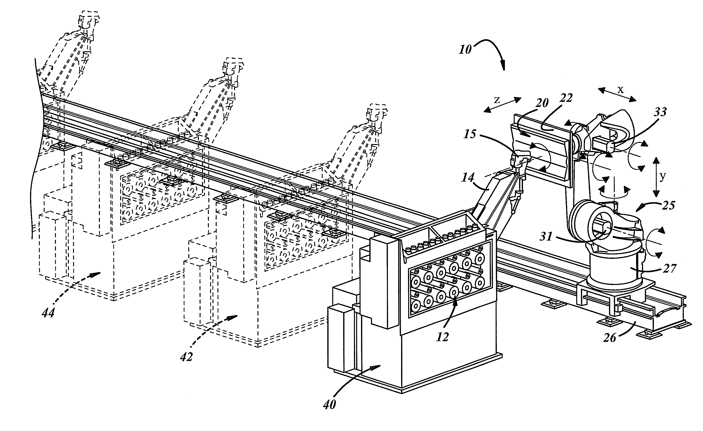
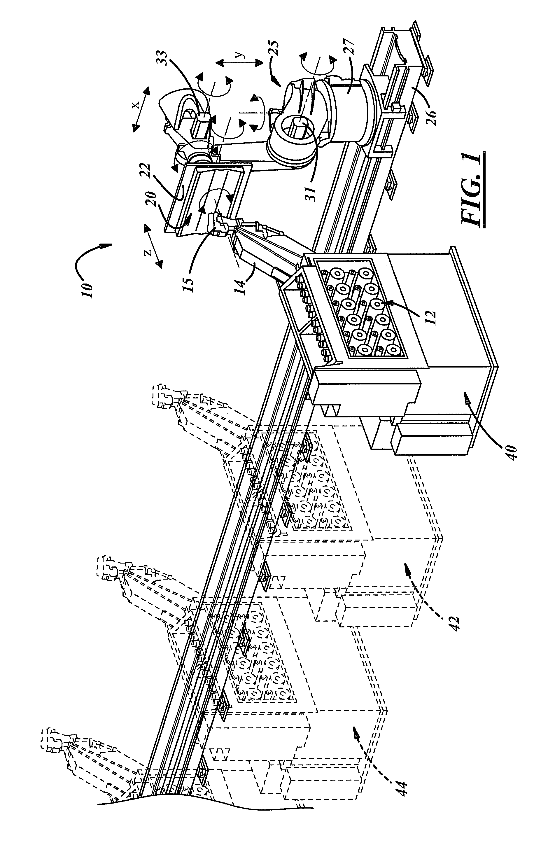
[0011]Turning now to the drawing figures, FIG. 1 shows a robotic fiber placement cell with a stationary dispensing head and creel generally designated by the reference numeral 10. The cell comprises a creel 12 that is mounted in a fixed position on the floor. A fixed arm 14 is mounted next to the creel 12, and a fiber placement dispensing head 15 is mounted on the end of the arm 14 that is remote from the creel. Although not shown, an operator's platform may be positioned adjacent to the creel 12, and a control panel for operating and monitoring the fiber placement cell may be located on the operator's platform.

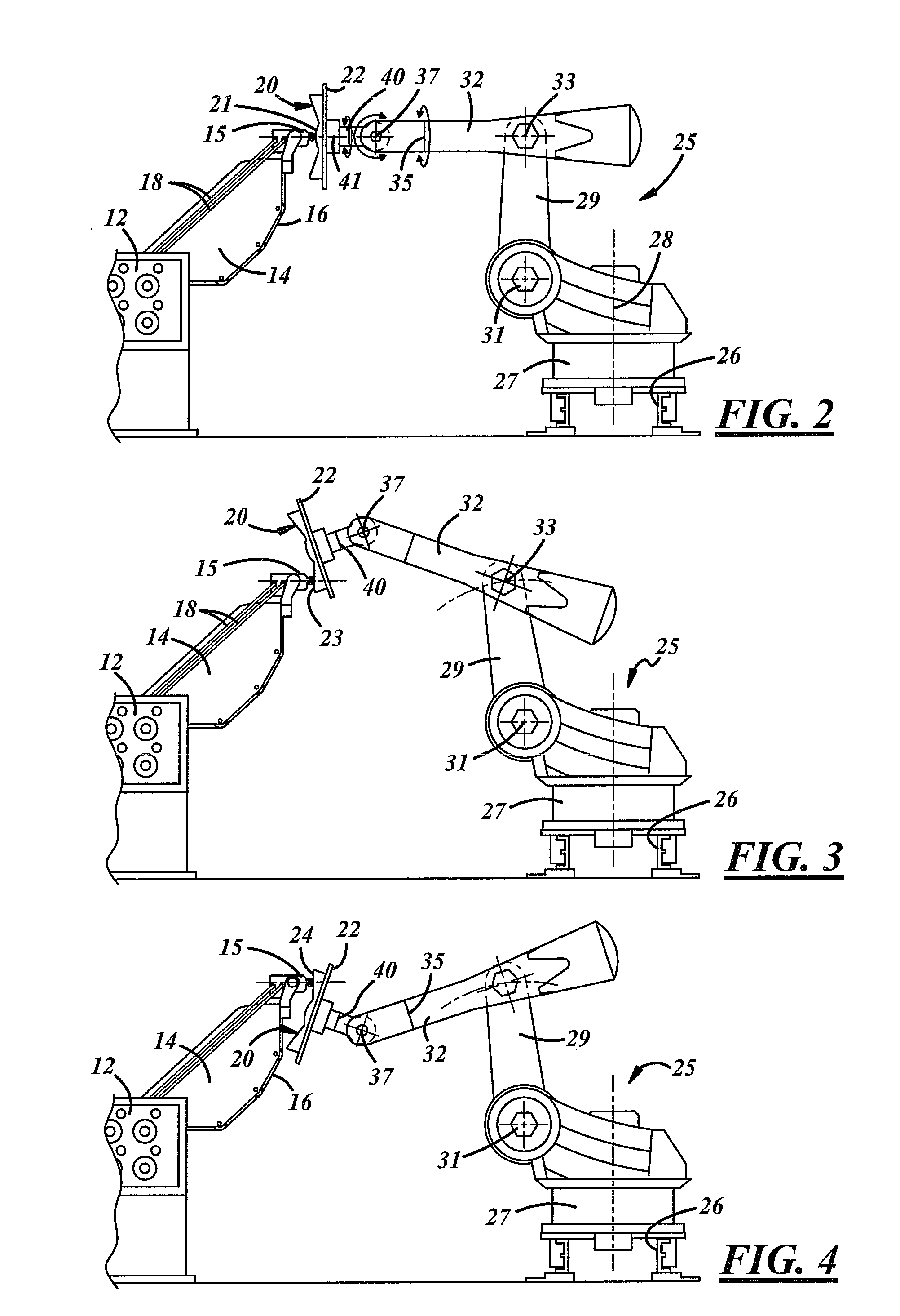
[0012]The creel 12 utilizes standard spool mounting and tensioning components (not shown) to control the flow of the fiber from the creel to the head 15. As best seen in FIGS. 2-4, tow material 16 is routed from the creel 12 to the dispensing head 15 in a nearly straight line along the length of the arm 14, without twisting or changing direction or length as is normally requi...


PUM

PropertyMeasurementUnit
Lengthaaaaaaaaaa

Abstract

A system for applying composite fiber to a lay-up tool has a fixed creel for supplying fiber to the fiber placement dispensing head and a fixed arm having a first end attached to the creel and having a second end attached to the dispensing head. The dispensing head is fixed on the end of the arm. A robot having a first and second pivot axis and at least a first wrist supports the lay-up tool. The robot manipulates the tool for application of fiber from the head to the tool. Manipulating the tool instead of the dispensing head allows the path length for the fiber between the creel and head to be fixed in length and orientation during application of fiber to the tool.

Description

FIELD OF THE DEVICE[0001]The device relates to a fiber placement cell for making fiber composite structures in which the dispensing head and creel are stationary relative to each other and the lay-up tool is mounted on the end of a movable robot arm.BACKGROUND[0002]Present day fiber placement systems for making composite parts use a stationary or rotating tool or workpiece with the dispensing head mounted on the end of a highly movable robot arm or other multi-axis manipulation system. U.S. Pat. No. 5,022,952 to Vaniglia shows a typical fiber placement system of this type. The robot arm or multi-axis system manipulates the dispensing head to apply the fiber to the tool in the desired pattern. In some systems, the tool may be mounted for rotation. The fiber is supplied from a creel that typically is fixed to the first axis of the manipulator, and the manipulation of the head by the robot arm requires that the fiber travel along a path that is continually changing in length and orient...

Claims


Application Information

Patent Timeline
IPC IPC(8): B32B41/00B32B37/00
CPCY10T156/1348B29C70/38
Inventor BORGMANN, ROBERT E.ALBERS, STEPHEN J.KNEIFEL, II, R. WILLIAM
Owner FIVES MACHINING SYST
Why Eureka
Try Eureka