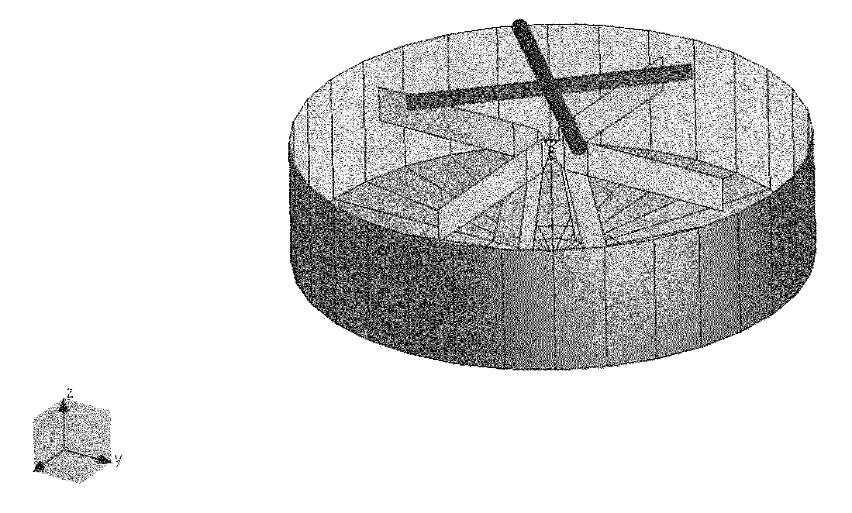
Dual circularly polarized antenna
a circularly polarized antenna and circular antenna technology, applied in the field of receiving antennas, can solve the problems of difficult to obtain a good axial ratio over a wide angular range (over the upper hemisphere) with virtually any circularly polarized antenna
- Summary
- Abstract
- Description
- Claims
- Application Information
AI Technical Summary
Benefits of technology
Problems solved by technology
Method used
Image

Examples
Embodiment Construction
[0047]Various features and advantageous details are explained more fully with reference to the nonlimiting embodiments that are illustrated in the accompanying drawings and detailed in the following description. Descriptions of well known starting materials, processing techniques, components, and equipment are omitted so as not to unnecessarily obscure the invention in detail. It should be understood, however, that the detailed description and the specific examples, while indicating embodiments of the invention, are given by way of illustration only, and not by way of limitation. Various substitutions, modifications, additions, and / or rearrangements within the spirit and / or scope of the underlying inventive concept will become apparent to those skilled in the art from this disclosure.
[0048]The improved antennas described herein may have better broadband impedance characteristics for improved delivery of received signal power to the quadrature hybrid and the GNSS receivers. The anten...
PUM
 Abstract
Description
Claims
Application Information