Touch Screen Shield

Active Publication Date: 2011-11-17
RACING OPTICS
View PDF17 Cites 180 Cited by
  • Summary
  • Abstract
  • Description
  • Claims
  • Application Information

AI Technical Summary

Benefits of technology

[0015]The shield may further comprise one or more transparent sacrificial layers peelably removable from each other and the first side of the first transparent layer so that a top most sacrificial layer may be removed as desired. The first and second transparent layers may be thi...

Problems solved by technology

The sacrificial layers may be removed one at a time fro...

Method used


Image

  • Touch Screen Shield
  • Touch Screen Shield
  • Touch Screen Shield

Examples


Embodiment Construction

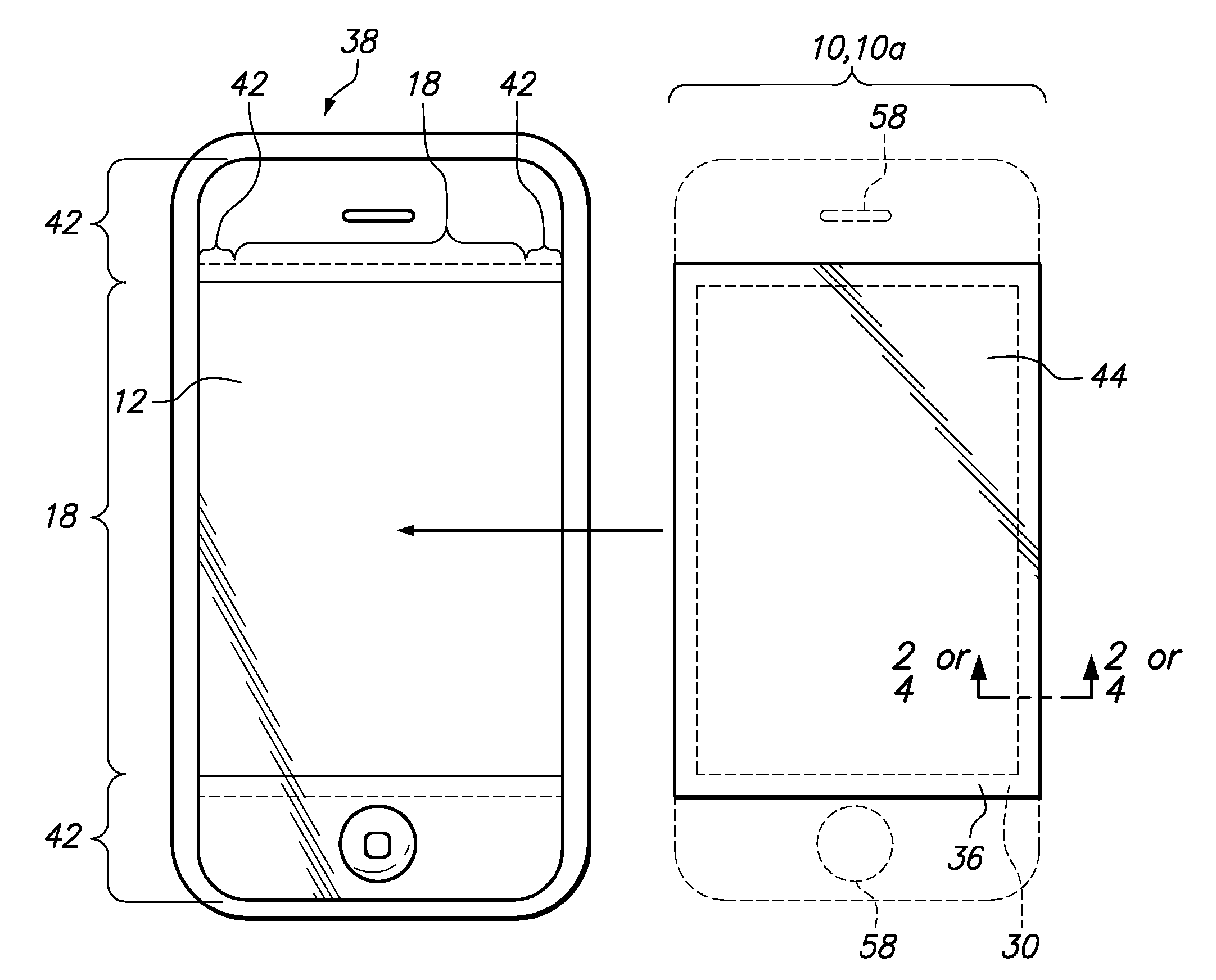
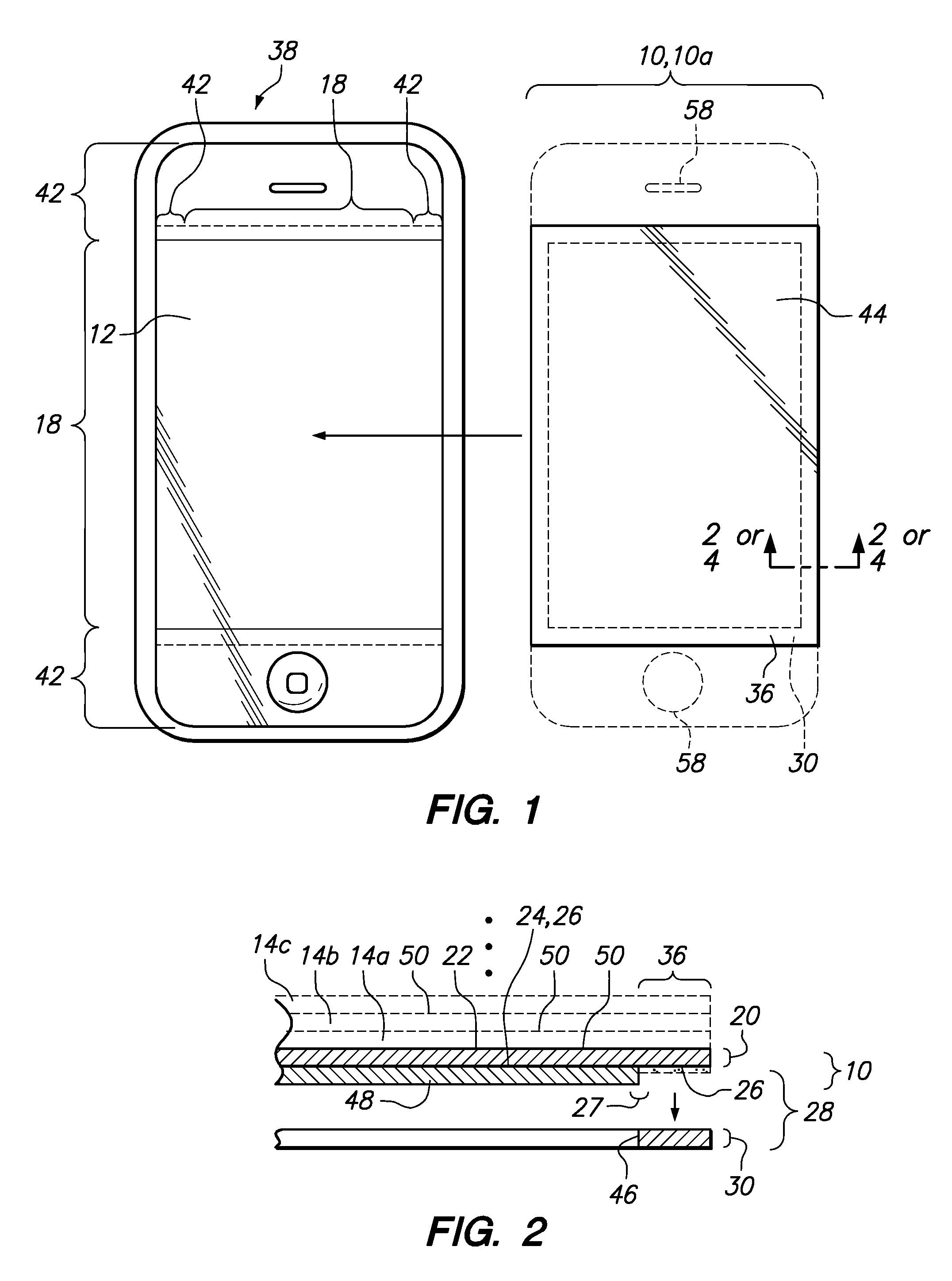
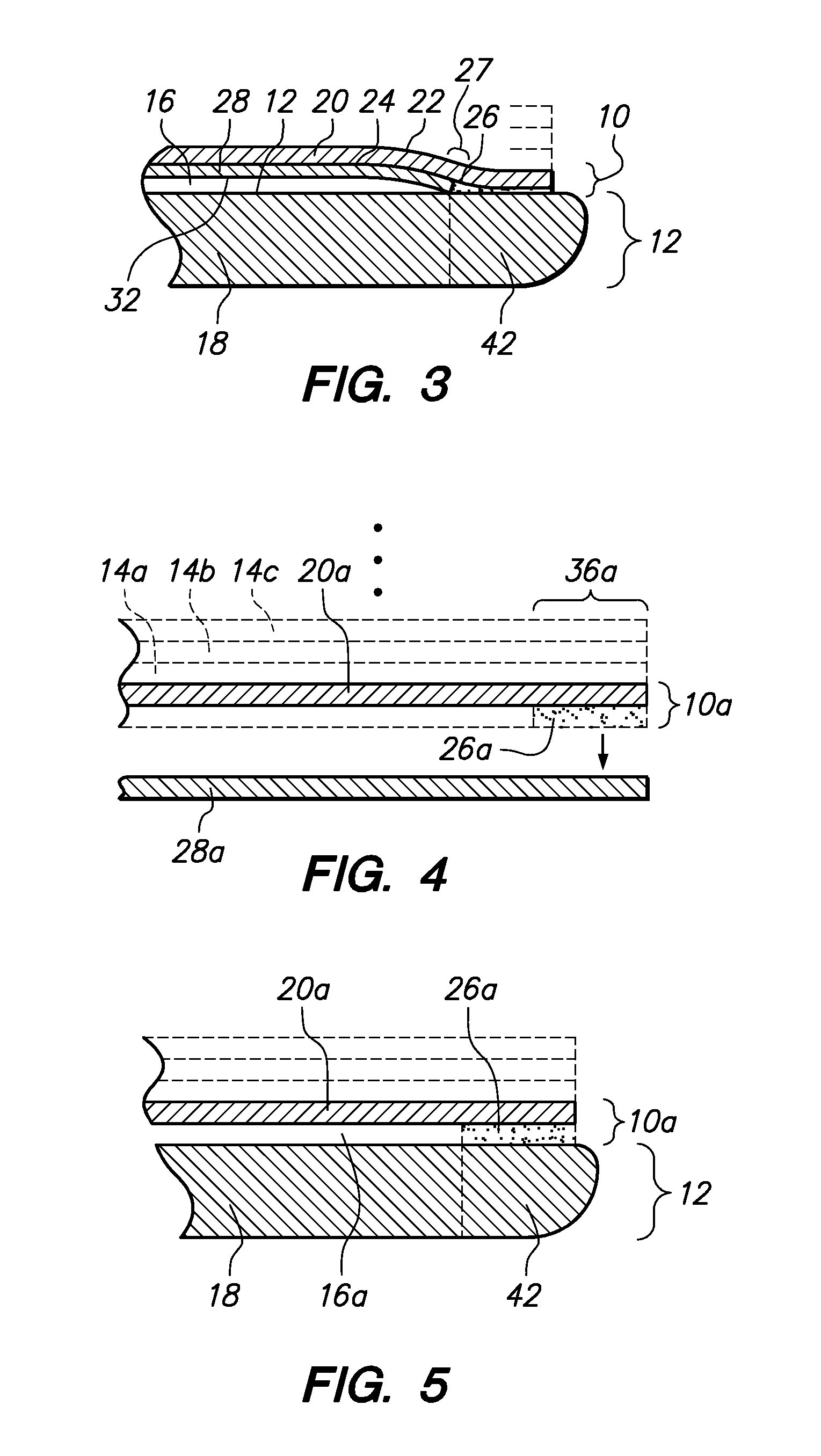
[0035]Referring now to the drawings, a shield 10 for a touch sensitive screen 12 is shown. The shield 10 protects the touch sensitive screen 12 from scratches, impacts, etc. The shield 10 is damaged instead of the touch sensitive screen 12. When the shield 10 is scratched, dented, etc. to a degree that makes viewing the touch sensitive screen 12 unacceptable for the user, the shield 10 may be replaced with a new shield 10. Optionally, the shield 10 may have one or more sacrificial layers 14 which may be individually peeled off from each other starting from the top most layer going down to the base shield 10 as the top most sacrificial layer 14 is damaged. The sacrificial layers 14a-h may be mounted on top of the shield 10, 10a. When the shield 10 is attached to the touch sensitive screen 12, an air gap 16 (see FIG. 3) may be formed between the shield 10 and an active area 18 of the touch sensitive screen 12. The air gap 16 eliminates unwanted optical artifacts such as trapped area b...


PUM


Abstract

A shield that is attachable to a touch sensitive screen is disclosed. The shield may be attached to the touch sensitive screen only at its outer peripheral portion. An air gap is enclosed between the shield and the touch sensitive screen to form a planar air bearing. The shield preferably does not touch the active area of the touch sensitive screen when the user is not touching the shield but only viewing the touch sensitive screen through the shield. This mitigates unwanted optical artifacts such as trapped air bubbles, Newton rings and chromatic interference while maintaining the sensitivity of the touch sensitive screen.

Description

CROSS-REFERENCE TO RELATED APPLICATIONS[0001]Not ApplicableSTATEMENT RE: FEDERALLY SPONSORED RESEARCH / DEVELOPMENT[0002]Not ApplicableBACKGROUND[0003]The present invention relates to transparent films applied to touch sensitive screens for impact and / or scratch protection.[0004]Electronic devices such as the iPhone have a touch sensitive screen by which the user may operate the electronic device. The touch sensitive screen displays electronic buttons and search boxes that the user can select by touch. These touch sensitive screens are very large and subject to cracking and scratching during normal use by the user as well as when the electronic device is dropped. The resulting damage may be costly to repair and may require replacement of the entire electronic device or phone. Accordingly, there is a need for a low cost device that will cushion and absorb an impact that could break or scratch the glass face of the electronic device and yet not interfere with the functionality and sensi...

Claims


Application Information

Patent Timeline
IPC IPC(8): G06F3/041
CPCG06F3/041G06F2203/04103G06F2203/04107Y10T156/10Y10T156/1052Y10T428/24744G06F1/1633Y10T428/14Y10T428/1471Y10T428/239Y10T428/24331G06F3/0412G06F2200/1634G06F1/1637G06F1/1643B32B7/05B32B3/06B32B37/0076B32B2250/02B32B2457/20B32B2571/00B32B37/12B32B37/18B32B38/10B32B2457/208B32B2551/00B32B7/06B32B7/12
Inventor WILSON, STEPHEN S.WILSON, BARTWILSON, SETH
Owner RACING OPTICS
Why Eureka
Try Eureka