

Driver drowsiness detection and verification system and method
a technology of driver drowsiness and verification system, which is applied in the direction of brake system, electric device, tractors, etc., can solve the problems of increasing the risk of human error, fatalities and injuries, and affecting the individual's ability to operate a vehicle safely
- Summary
- Abstract
- Description
- Claims
- Application Information
AI Technical Summary
Problems solved by technology
Method used
Image

Examples
Embodiment Construction
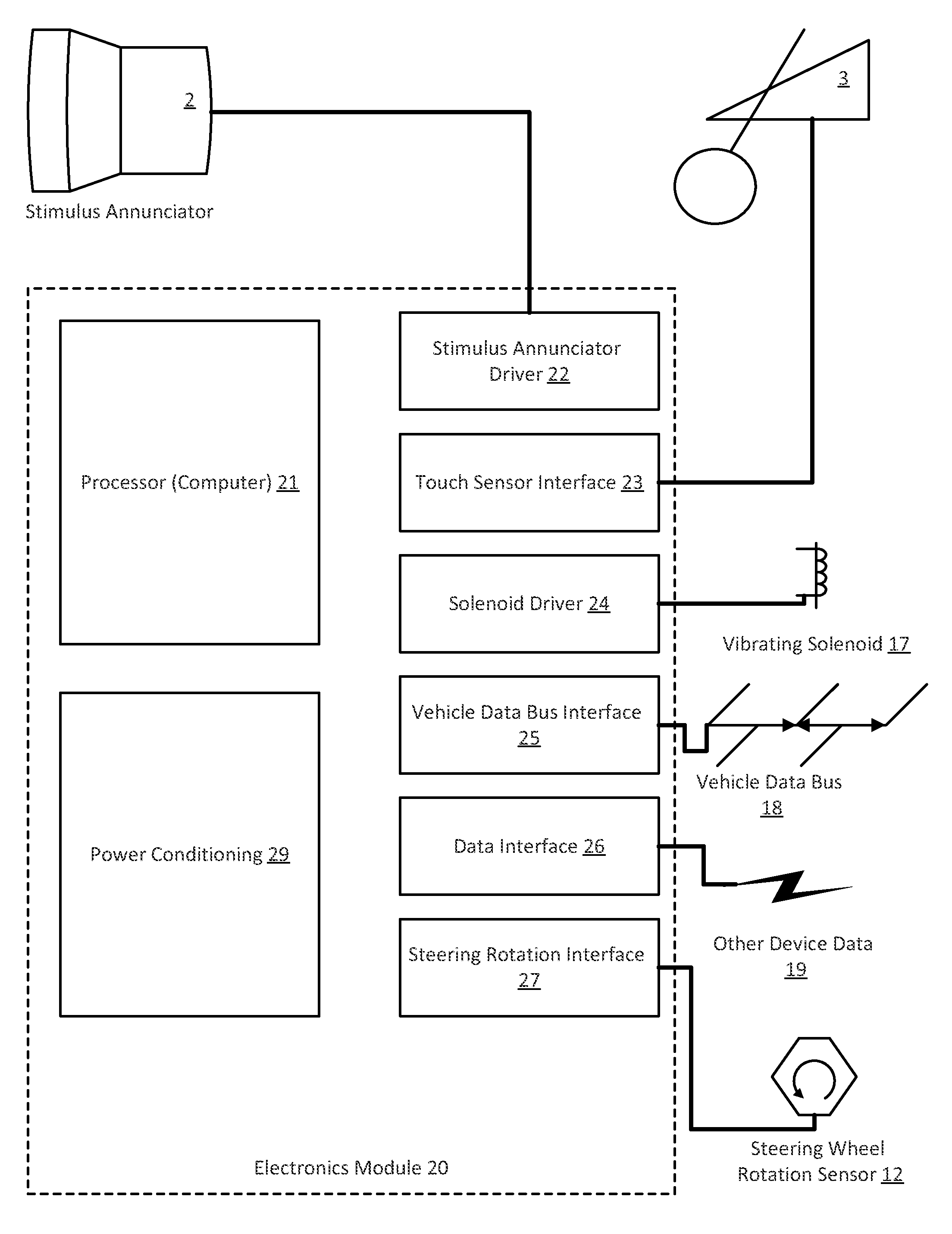
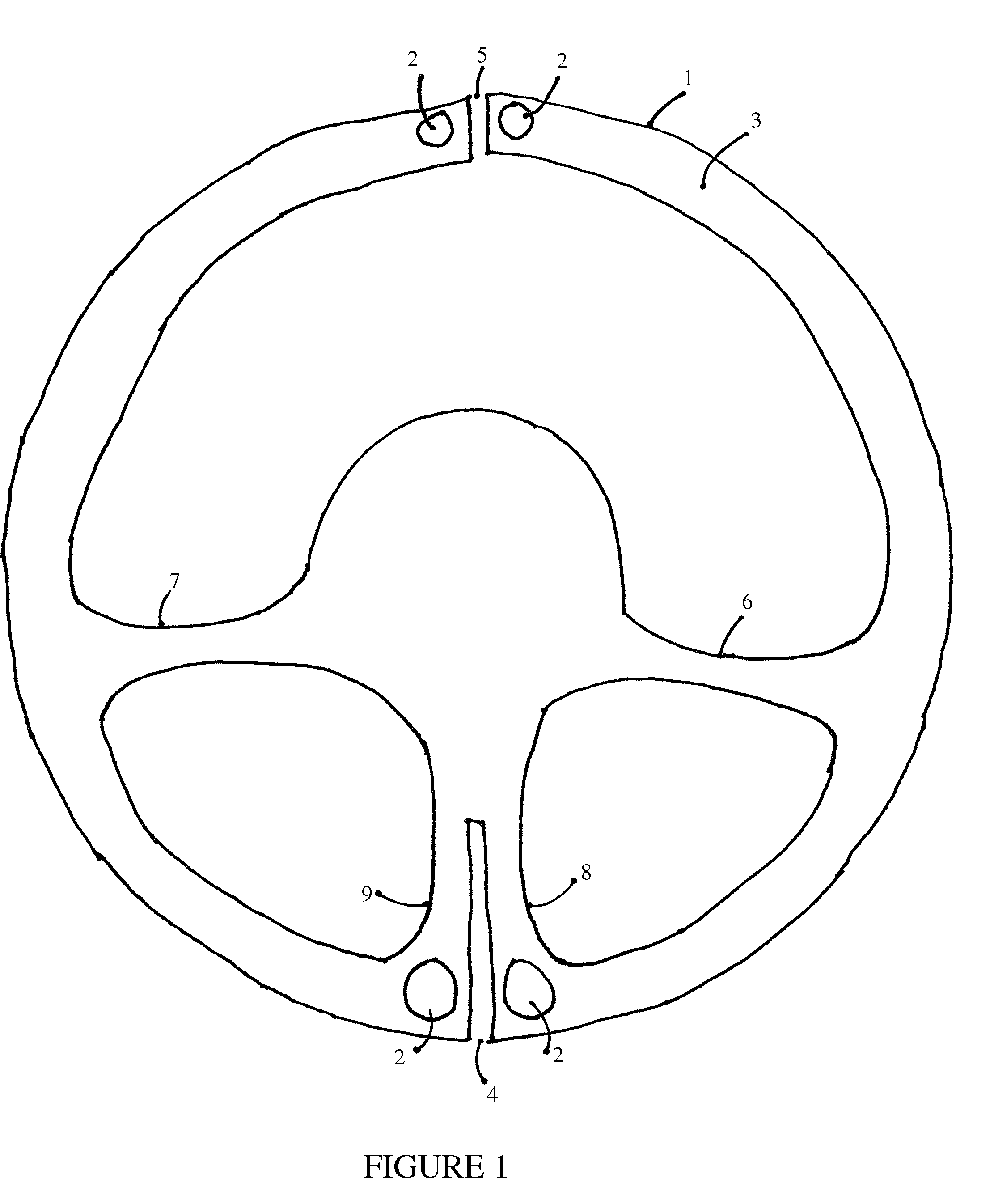
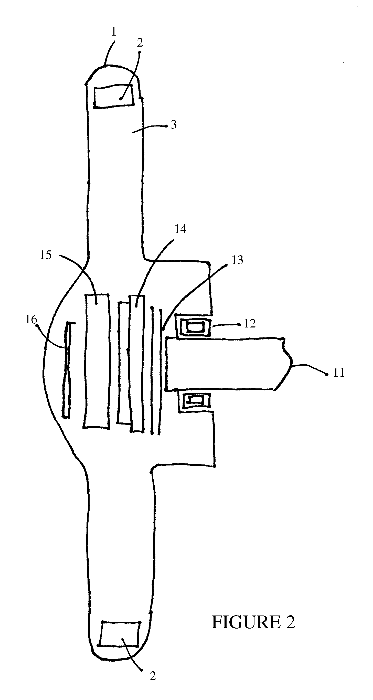
The present invention relates generally to motor vehicle safety equipment and, more specifically, to the driver / motor vehicle interface. Many specific details of certain embodiments of the invention are set forth in the following description and in FIGS. 1, 2, and 3 to provide a thorough understanding of such embodiments. One skilled in the art, however, will understand that the present invention may have additional embodiments, or that the present invention may be practiced without several of the details described in the following description.
When broken down into its simplest elements, the ability of an individual to respond to stimuli can be most readily measured by presenting a simple stimulus and measuring the reaction time necessary to make an affirmative and uncomplicated response to that stimulus. In a laboratory setting, where the repeated testing of a subject can be performed without distracting a subject from the driving task, one system has gained almost universal accept...
PUM
 Abstract
Description
Claims
Application Information