

Organic light-emitting diodes
a light-emitting diode and organic technology, applied in the field of multi-layered organic light-emitting diodes, can solve the problems of reducing the life span of the element, obtaining a sufficient coating performance, and materials that are not easy to handle during processing, so as to improve the light-emitting efficiency of the light-emitting diode, and improve the light-emitting efficiency
- Summary
- Abstract
- Description
- Claims
- Application Information
AI Technical Summary
Benefits of technology
Problems solved by technology
Method used
Image

Examples
embodiment 1
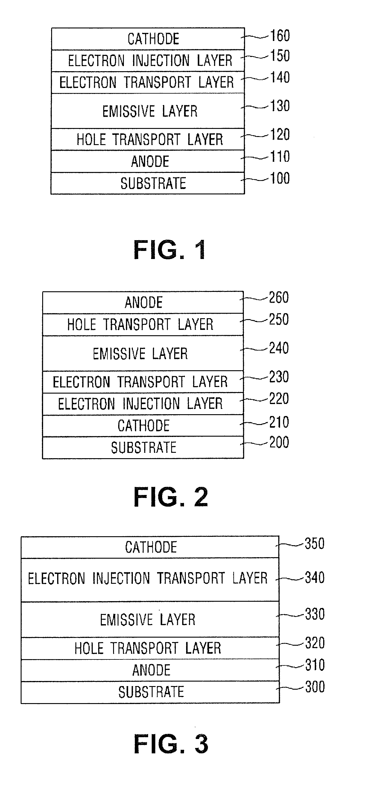
[0065]Anode: manufactured with indium tin oxide (ITO) glass, deionized water, acetone and isopropyl alcohol (IPA) are put into three beakers respectively, and ultrasonic cleaning is performed for 5 minutes by an ultrasonic cleaner. Then, washing and surface treatment are performed for one hour by using an ozone ultraviolet lamp of an ozone handler.
[0066]Hole transport layer: A PEDOT:PSS solution is dropped on the ITO glass, a spin coating is performed at 2000 rpm for 40 seconds, and then a heat treatment process is performed at a temperature of 200° C. for 5 minutes on a hot plate.
[0067]Emissive layer: phenyl substituted poly_para-phenylene vinylene known as “Super Yellow” (0.65 w % into toluene) or F8BT of light-emitting polymer is added to a toluene solution of 1 w %, a spin coating is performed for 30 seconds, and then baking is performed at a temperature of 70° C. for 1 hour on a hot plate.
[0068]Electron transport layer: ZnO nanoparticle of 60 mg / mm is put into 1-butanol, a spin...
embodiment 2
[0073]Anode: manufactured with indium tin oxide (ITO) glass, deionized water, acetone and isopropyl alcohol (IPA) are put into three beakers respectively, and ultrasonic cleaning is performed for 5 minutes by an ultrasonic cleaner. Then, washing and surface treatment are performed for one hour by using an ozone ultraviolet lamp of an ozone handler.
[0074]Hole transport layer: A PEDOT:PSS solution is dropped on the ITO glass, a spin coating is performed at 2000 rpm for 40 seconds, and then a heat treatment process is performed at a temperature of 200° C. for 5 minutes on a hot plate.
[0075]Emissive layer: phenyl substituted poly_para-phenylene vinylene known as “Super Yellow” (0.65 w % into toluene) or F8BT of light-emitting polymer is added to a toluene solution of 1 w %, a spin coating is performed for 30 seconds, and then baking is performed at a temperature of 70° C. for 1 hour on a hot plate.
[0076]Electron transport layer: ZnO nanoparticle of 60 mg / mm is put into 1-butanol, a spin...
embodiment 3
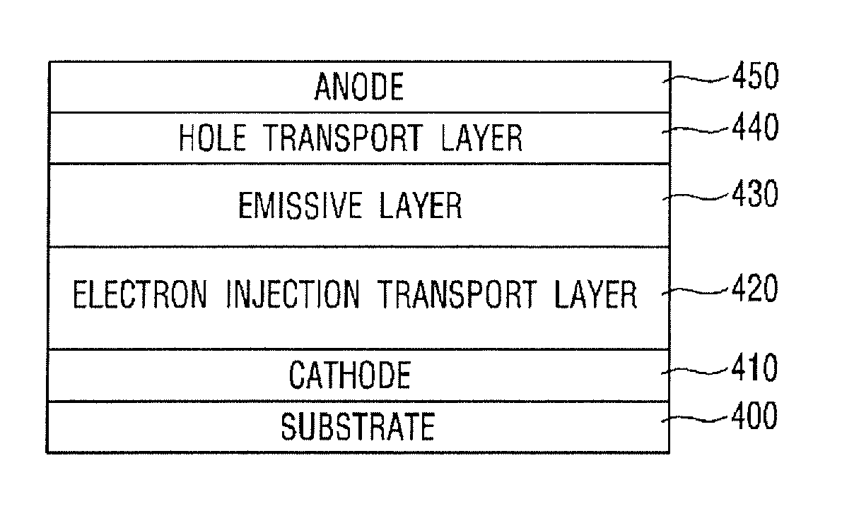
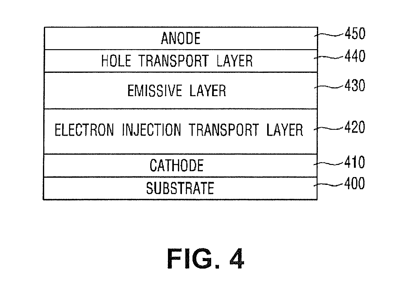
[0089]Cathode: manufactured with indium tin oxide (ITO) glass, deionized water, acetone and isopropyl alcohol (IPA) are put into three beakers respectively, and ultrasonic cleaning is performed for 5 minutes by an ultrasonic cleaner. Then, washing and surface treatment are performed for one hour by using an ozone ultraviolet lamp of an ozone handler.
[0090]Electron injection layer: A spin coating is performed at 4000 rpm for 30 seconds on a solution in which PFN
(Poly [9,9-bis[6-(N,N,N-trimethylammonium)-hexyl]fluorene-alt-co-phenylene]) polymer 0.2 w % dimethyl formamide (DMF) including ammonium ion is dissolved, and then baking is performed at a temperature of 80° C. for 30 minutes.
[0091]Electron transport layer: ZnO nanoparticle of 60 mg / mm is put into 1-butanol, a spin coating is performed on the dispersed solution at 2000 rpm for 30 seconds, and then baking is performed at a temperature of 80° C. for 30 minutes.
[0092]Emissive layer: phenyl substituted poly_para-phenylene vinylene...
PUM
 Abstract
- a substrate formed of glass or a flexible plastic material;
- an anode formed on the substrate;
- a hole transport layer formed on the anode;
- an emissive layer formed on the hole transport layer;
- an electron transport layer being formed on the emissive layer and including a ZnO nanoparticle;
- an electron injection layer being formed on the electron transport layer and including an ionic group; and
- a cathode formed on the electron injection layer.
Description
Claims
Application Information