
Imaging device for recognition and method of controlling the same

Active Publication Date: 2011-11-24
PANASONIC INTELLECTUAL PROPERTY CORP OF AMERICA
View PDF10 Cites 28 Cited by
  • Summary
  • Abstract
  • Description
  • Claims
  • Application Information

AI Technical Summary

Benefits of technology

[0013]The imaging device for recognition thus configured extends the exposure time in the case where the object region has a sufficient area, thereby increasing the light amount in the object region. Extending the exposure time is prone to incur a motion blur in the object region. However, the object region having a sufficiently large area enables a resolution required for an object recognition process and an object tracking process to be secured despite the increase in motion blur, and hence the object recognition process and the object tracking process are barely affected. On the other hand, the increase in light amount results in a higher SN ratio of the object region, thereby contributing to improving the accuracy of the object recognition process and the object tracking process.
[0036]Further, the imaging device for recognition reduces the aperture value in the case where the light amount is insufficient, thereby securing a light amount required for recognition.

Problems solved by technology

For example, an insufficient resolution or a poor SN ratio of the face leads to an unclear feature of the face, resulting in degraded recognition accuracy.

Method used


Image

  • Imaging device for recognition and method of controlling the same
  • Imaging device for recognition and method of controlling the same
  • Imaging device for recognition and method of controlling the same

Examples


embodiment 1

[0057]An imaging device for recognition according to a first embodiment of the present invention changes a shutter speed depending on an area, a moving speed and a light amount of a face region. More specifically, the imaging device for recognition according to the first embodiment reduces the shutter speed in the case where the face region has a large area.

[0058]The imaging device for recognition thus configured according to the first embodiment can stably recognize the face. Hereunder, the first embodiment of the present invention will be described referring to the drawings.

[0059]First, a structure of the imaging device for recognition 100 according to the first embodiment will be described.

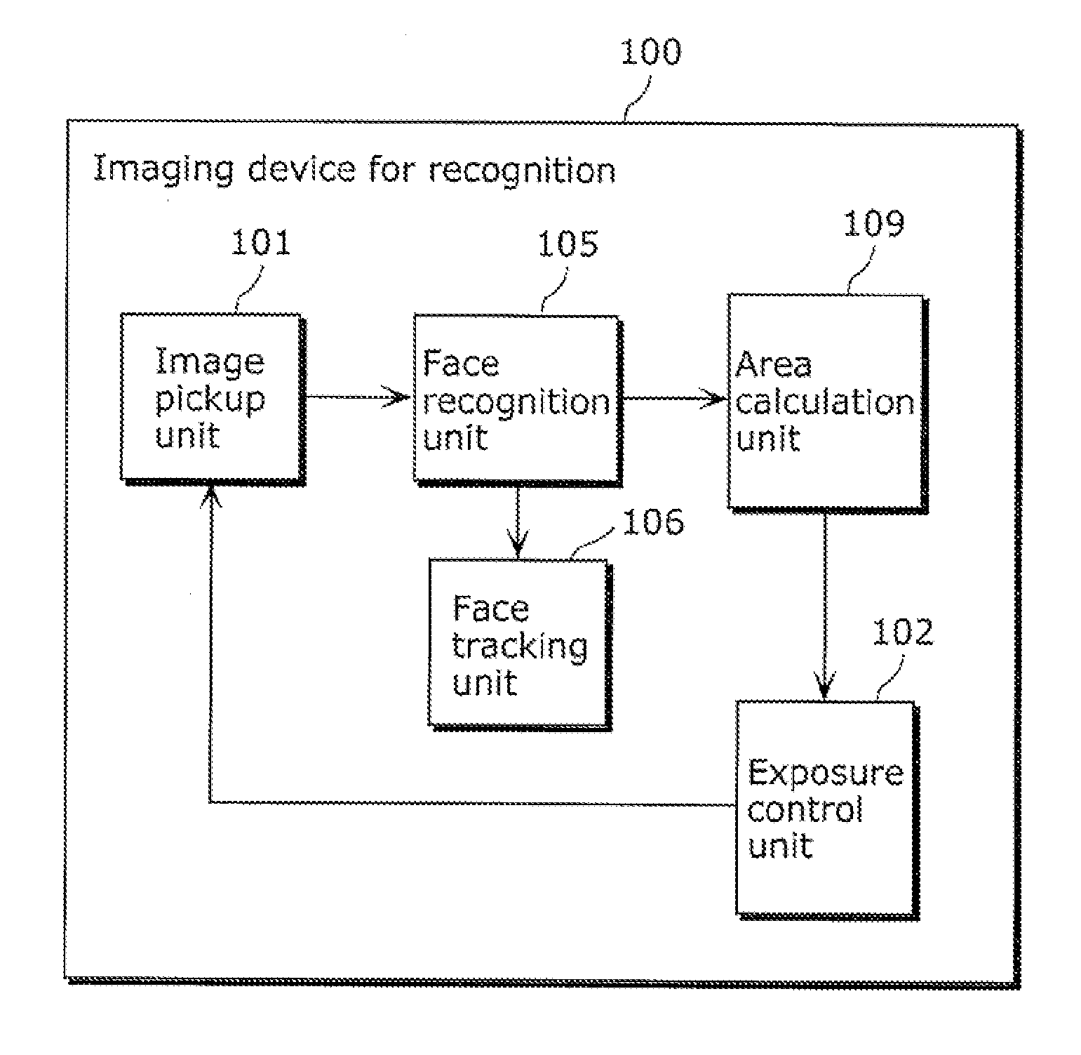
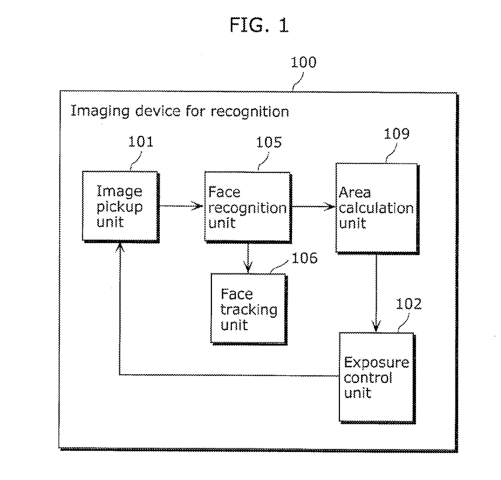
[0060]FIG. 1 is a block diagram of the imaging device for recognition 100 according to the first embodiment of the present invention.

[0061]The imaging device for recognition 100 shown in FIG. 1 may be, for example, a digital still camera, a digital video camera, a network camera, or a security ...

embodiment 2

[0124]An imaging device for recognition according to a second embodiment of the present invention changes a focusing position thereof, on the basis of the area of the face region. More specifically, the imaging device for recognition according to the second embodiment sets the focusing position at a position farther from the face, in the case where the face region has a large area.

[0125]Through such a process, the imaging device for recognition according to the second embodiment can stably perform the face recognition.

[0126]In the following passages, differences from the first embodiment will be primarily described, and the description already made above will not be repeated. Also, the same constituents will be given the same numeral.

[0127]FIG. 8 is a block diagram of the imaging device for recognition 100A according to the second embodiment of the present invention.

[0128]The imaging device for recognition 100A shown in FIG. 8 is different from the imaging device for recognition 100...

embodiment 3

[0149]An imaging device for recognition according to a third embodiment of the present invention changes an aperture value on the basis of the area and light amount of the face region. More specifically, the imaging device for recognition according to the third embodiment increases the aperture value in the case where the face region has a large area.

[0150]Through such a process, the imaging device for recognition according to the third embodiment can stably perform the face recognition.

[0151]In the following passages, differences from the first and the second embodiment will be primarily described, and the description already made will not be repeated. Also, the same constituents will be given the same numeral.

[0152]FIG. 12 is a block diagram of the imaging device for recognition 100B according to the third embodiment of the present invention.

[0153]The imaging device for recognition 1006 shown in FIG. 12 is different from the imaging device for recognition 100 of the first embodime...


PUM


Abstract

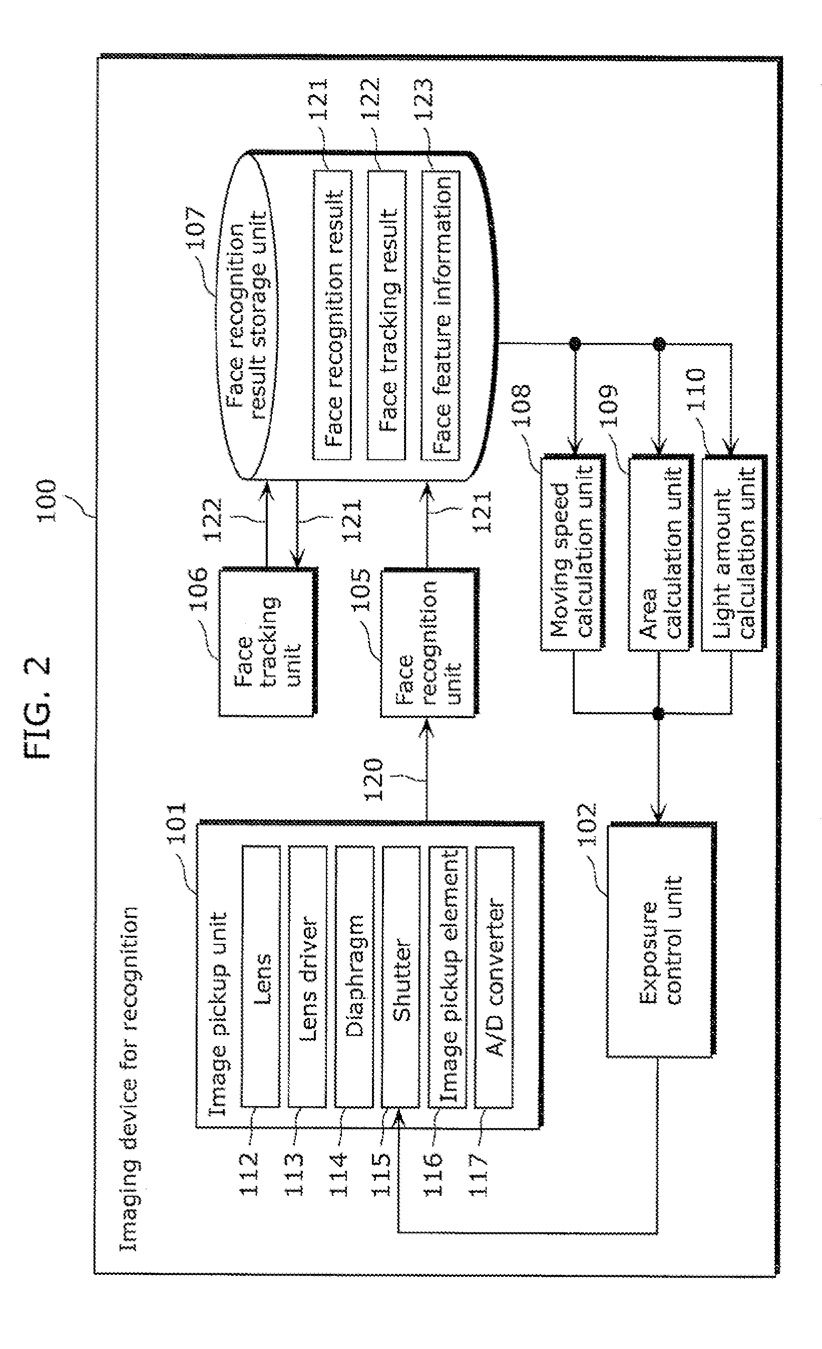
An imaging device for recognition (100) includes an image pickup unit (101) that sequentially generates a plurality of images by shooting an object, a face recognition unit (105) that recognizes, in each of the plurality of images, an object region in which the object is located in the image, a face tracking unit (106) that tracks the object region across the plurality of images, an area calculation unit (109) that calculates an area of the object region, and an exposure control unit (102) that sets a first exposure time for the image pickup unit (101) in the case where the area is smaller than a first threshold, and sets a second exposure time longer than the first exposure time in the case where the area is equal to or larger than the first threshold.

Description

TECHNICAL FIELD [0001]The present invention relates to an imaging device for recognition that recognizes an object in an image, and a method of controlling the same.BACKGROUND ART [0002]Latest advancement in function of digital cameras is really amazing. These days, many digital cameras are capable of recognizing the face of a non-specific person, as well as the face of a specific person. Also, some digital cameras can recognize a moving face in a through-the-lens image of the camera successively from time to time, thereby tracking the face in the image to be shot. Thus, further progress in function of digital cameras is being attempted.[0003]It is known in the field of face recognition technique that a resolution and a signal / noise (SN) ratio of the face play an important role in recognition accuracy. For example, an insufficient resolution or a poor SN ratio of the face leads to an unclear feature of the face, resulting in degraded recognition accuracy. The resolution and the SN...

Claims


Application Information

Patent Timeline
IPC IPC(8): G06K9/00H04N5/232H04N5/235G06V10/141
CPCG03B7/093G03B15/00G06K9/00255H04N5/238H04N5/23212H04N5/23219H04N5/2353G06K9/2027G06V40/166G06V10/141H04N23/675H04N23/61H04N23/611H04N23/75H04N23/73
Inventor FUJII, TAKASHI
Owner PANASONIC INTELLECTUAL PROPERTY CORP OF AMERICA
Learn More