Modular Thermal Energy Retention and Transfer System

a technology of thermal energy storage and transfer system, applied in the field of modules, can solve the problems of increasing the cost of energy production, driving the capital expenditure of energy production, and increasing the economic demand for consumable energy

Inactive Publication Date: 2011-11-24
GOODMAN TRAVIS
View PDF18 Cites 59 Cited by
  • Summary
  • Abstract
  • Description
  • Claims
  • Application Information

AI Technical Summary

Benefits of technology

[0017]The various thermal retainers of the modular thermal units are configured to be positionable proximate one another such that thermal energy is transferable between substantially adjacent thermal retainers. The conditioning pipes are in fluidic communication with one another, such that conditioning fluid is capable of passing sequentially through each of the conditioning pipes of the modular thermal energy transfer system, thereby allowing thermal exchange between the conditioning fluid and each of the thermal retainers. Likewise, the usable fluid pipes are in fluidic communication with one another, such that usable fluid is capable of passing sequentially through each of the usable fluid pipes of the modular thermal energy transfer system, thereby allowing thermal exchange between the usable fluid and each of the thermal retainers.

Problems solved by technology

In the field of energy management, energy usage during peak periods generally drives the capital expenditures of energy production and imposes increased economic demand on consumable energy.
In several applications, increased demand for consumable energy during peak periods often results in increased costs of energy production, and in certain applications, a shortage of available consumable energy.
For example, in the use of thermal energy transfer technology for thermally conditioning ambient fluids such as water or air, it is generally more difficult and / or more costly to cool ambient fluids to a desirable temperature during particularly hot periods such as the summer, and conversely, it is often more difficult and / or more costly to heat ambient fluids during cold periods such as the winter, due in part to the increased differences between the ambient temperature during these periods and the desired temperature for the thermally conditioned fluids.
Likewise, due to increased differences between ambient temperature and the desired temperature for thermally conditioned fluids, it is often more difficult and / or more costly to cool ambient fluids during the relative warmth of the day, and conversely, it is often more difficult to heat such ambient fluids during the relative cool of the night.
Several of the prior art devices are limited in their adaptability to the need for thermal energy storage devices of various sizes, shapes, and capacities.
For example, the thermal energy storage devices disclosed in the '731 patent, the '782 patent, the '650 patent, and the '659 patent, as discussed above, each require that the device be constructed and permanently installed at the site of the intended usage of the device, thus limiting the ability to expand or reduce the size and / or capacity of the device following initial installation.
Moreover, several of the prior art devices are limited in their ability to be used for collection, storage, and dispensation of thermal energy for use in heating and / or cooling both liquid and gas fluids.
However, many known renewable sources of energy are intermittent and are therefore not always available coincidentally with the demand for energy.
Some residential distribution networks are not designed to accommodate such large power flows.
Such natural gas fired turbines are typically extremely inefficient due to the amount of thermal energy wasted by the natural gas fired turbines due to the theoretical and practical limits imposed by the thermodynamic properties of the natural gas turbines.

Method used


Image

  • Modular Thermal Energy Retention and Transfer System
  • Modular Thermal Energy Retention and Transfer System
  • Modular Thermal Energy Retention and Transfer System

Examples


Embodiment Construction

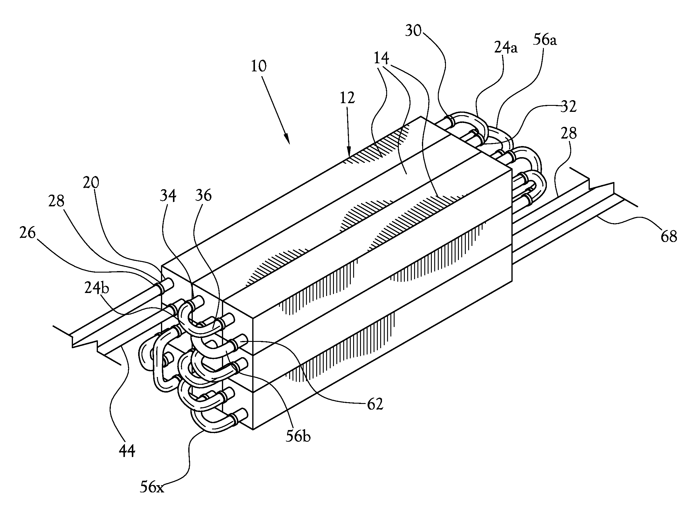
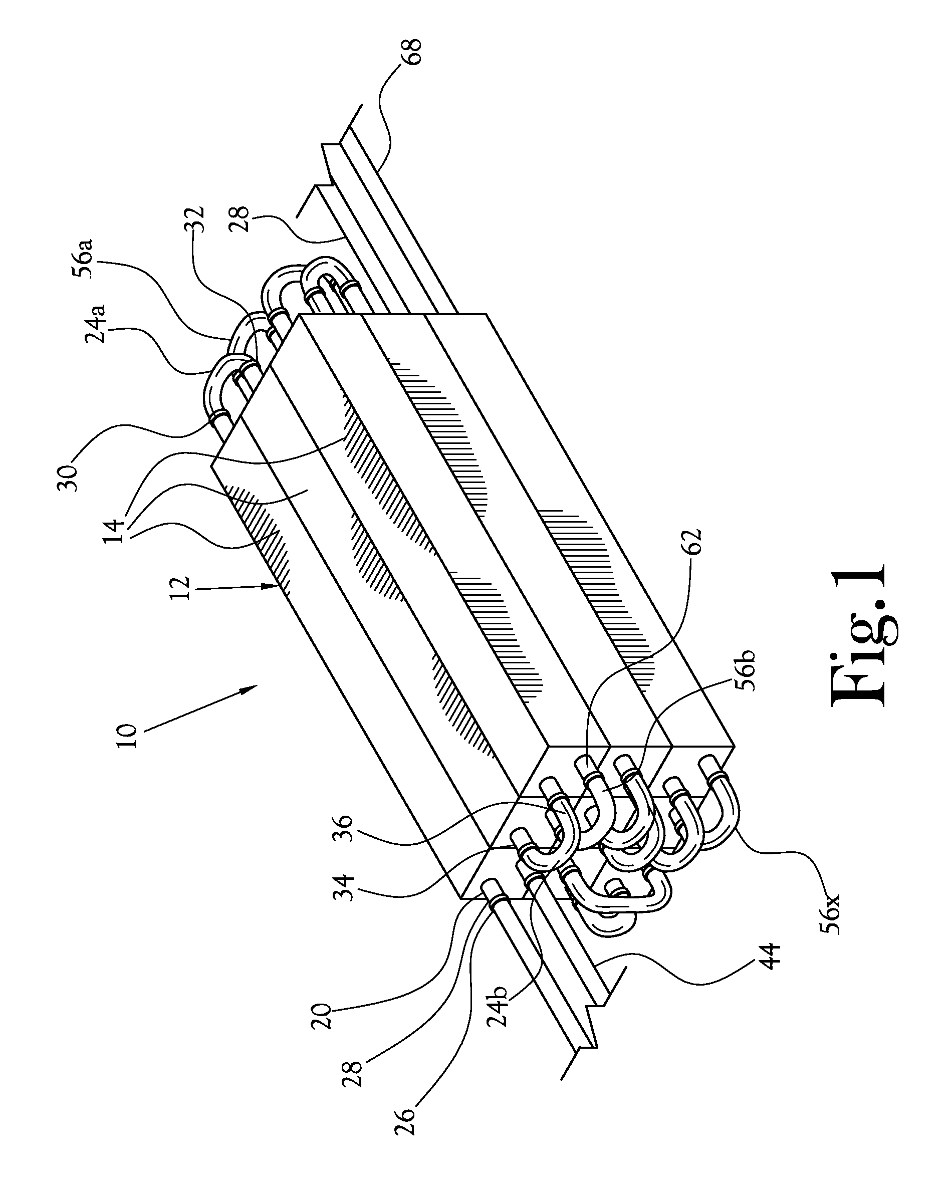
[0037]The present invention provides a modular thermal energy transfer system for collecting and / or supplying thermal energy during a first time frame, for retaining at least a portion of the thermal energy until a second time frame, and for transferring at least a portion of the thermal energy to a usable fluid during the second time frame. More specifically, the present invention provides a modular apparatus for transferring thermal energy between a first fluid and a medium, and / or supplying thermal energy and transferring the generated thermal energy to the medium, to create a temperature differential in the medium, maintaining the temperature differential in the medium, and applying the temperature differential to a second fluid to change the temperature in the second fluid.

[0038]A perspective view of one embodiment of the modular thermal energy transfer system constructed in accordance with the various features of the present invention is illustrated generally at 10 in FIG. 1. ...


PUM


Abstract

Described is a modular thermal energy transfer system. The modular thermal energy transfer system includes a plurality of modular thermal units, each modular thermal unit having a thermal retainer with a conditioning pipe and a usable fluid pipe disposed therein. The conditioning pipes are in fluidic communication with one another, and the usable fluid pipes are in fluidic communication with one another. The conditioning pipes are adapted to carry a conditioning fluid therethrough and to allow transfer of thermal energy between the thermal retainers and the conditioning fluid. The usable fluid pipes are adapted to carry a usable fluid therethrough and to allow the transfer of thermal energy between the thermal retainers and the usable fluid. The various thermal retainers of the modular thermal units are configured to be positionable proximate one another such that thermal energy is transferable between substantially adjacent thermal retainers.

Description

CROSS-REFERENCE TO RELATED APPLICATIONS[0001]Not ApplicableSTATEMENT REGARDING FEDERALLY SPONSORED RESEARCH OR DEVELOPMENT[0002]Not ApplicableBACKGROUND OF THE INVENTION[0003]1. Field of the Invention[0004]This invention pertains to a modular system for collecting and / or generating and retaining thermal energy and for transferring the thermal energy to a usable fluid.[0005]2. Description of the Related Art[0006]In the field of energy management, energy usage during peak periods generally drives the capital expenditures of energy production and imposes increased economic demand on consumable energy. It will be understood that a “peak period” is a time frame within which there is a usual and predictable spike in demand for electricity from a given electrical grid. In several applications, increased demand for consumable energy during peak periods often results in increased costs of energy production, and in certain applications, a shortage of available consumable energy. For example, ...

Claims


Application Information

Patent Timeline
Patent Type & Authority Applications(United States)
IPC IPC(8): F24H7/04F28D15/00F28D17/00
CPCF24D17/0005F24D2200/08F24D2200/14F24D2200/18F24D2200/26F24D2200/31Y02B10/70F28D19/04F28D20/00F28D20/0056F28F21/04Y02E60/142Y02B10/20F24H7/0466Y02B30/18Y02E60/14
Inventor GOODMAN, TRAVIS
Owner GOODMAN TRAVIS
Why Eureka
Try Eureka