Microalgae Growth Pond Design

a technology of microalgae and growth pond, which is applied in specific use bioreactors/fermenters, biochemical apparatus and processes, and after-treatment of biomass, etc. it can solve the problems of weed algae, bacteria or predators that would otherwise diminish algae production, and the time available for growth of weed algae, bacteria or predators, etc., and achieves the effect of reducing the number of alga

Inactive Publication Date: 2011-11-24
GENERAL ATOMICS
View PDF6 Cites 11 Cited by
  • Summary
  • Abstract
  • Description
  • Claims
  • Application Information

AI Technical Summary

Benefits of technology

[0012]At least one injector can be provided with the raceway pond to add fluid medium to the pond at a selected point(s) along the length of the raceway. The purpose for adding the fluid medium is two-fold. First, the addition of fluid medium is done to maintain the depth of the fluid medium substantially constant in the channels (e.g. 7.5 cm). Second, the controlled addition of fluid medium, together with the tapered construction of the first channel, provide for the maintenance of a pre-determined concentration of microalgae in the fluid medium (e.g. approximately 1.5 grams per liter). These considerations, along with the dimensions and structural aspects given above for the channels, are intended to ensure an operational net oil productivity from algae grown in the raceway pond that is in a range of 15-50 g / m2 / day.

Problems solved by technology

The import here is that with a high consumption of available resources by the microalgae, the time available for growth of weed algae, bacteria or predators that would otherwise diminish algae production, is limited.
It has been determined, however, this is not the case.
A problem with shallow ponds, however, is that typical means used for circulating the fluid medium are generally ineffective when pond depths are in the 7.5-10 cm range.
For example, paddle wheels are typically not effective for this purpose with pond depths less than 20 cm.
On this point, the larger the area, the more the unevenness in depth across the culture area, which can be a drawback in terms of productivity.

Method used


Image

  • Microalgae Growth Pond Design
  • Microalgae Growth Pond Design

Examples


Embodiment Construction

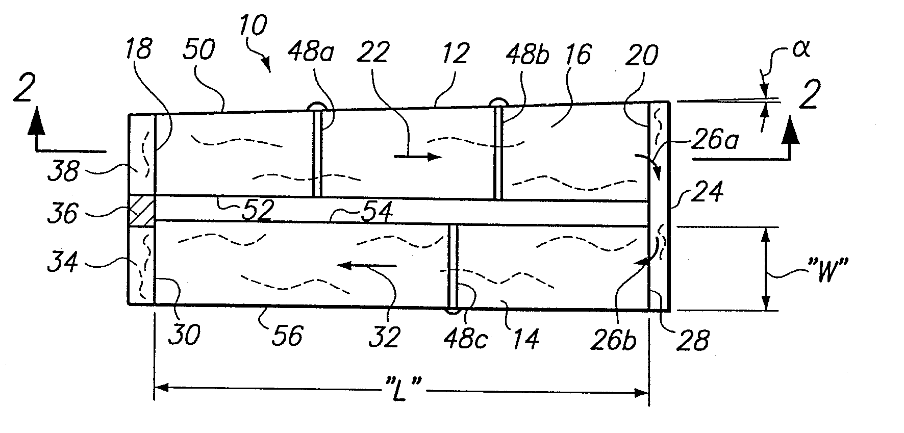
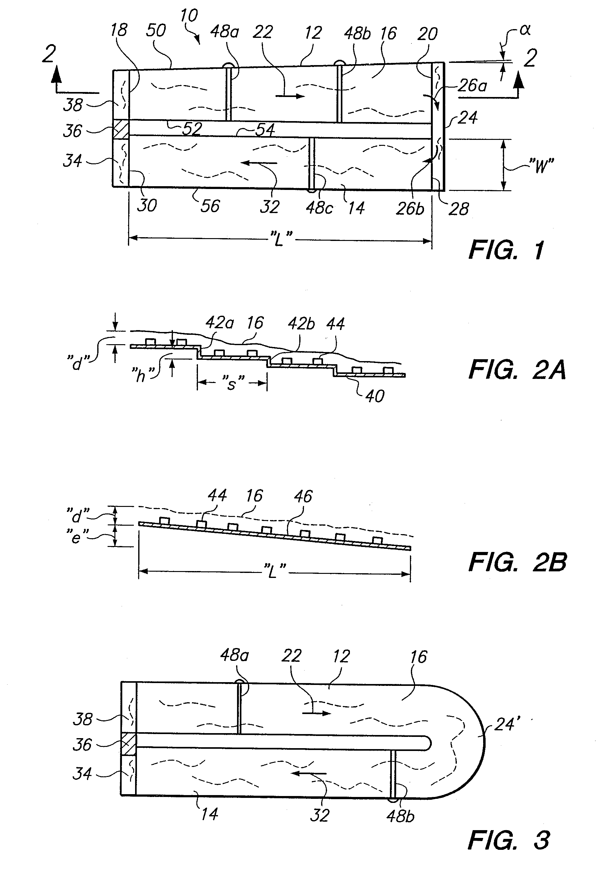
[0018]Referring initially to FIG. 1 a raceway pond in accordance with the present invention is shown and is generally designated 10. Specifically, in FIG. 1 it can be seen the pond 10 includes a first channel 12 and a second channel 14 that are shown juxtaposed in a side-by-side relationship with one another. Further, it is shown that the channels 12 and 14 are in fluid communication with each other and that a fluid medium 16 flows continuously from one to the other. As will be appreciated by the skilled artisan, the arrangement of the channels 12 and 14 shown in FIG. 1 is only exemplary. Depending on topography of the terrain where the pond 10 will be used, and the ability to satisfy other requirements of the present invention, the channels 12 and 14 can have any of various arrangements.

[0019]In greater detail, FIG. 1 shows that the fluid medium 16 flows in the first channel 12 from an upstream end 18 to a downstream end 20, as indicated by the arrow 22. After flowing through the f...


PUM

PropertyMeasurementUnit
angleaaaaaaaaaa
concentrationaaaaaaaaaa
depthsaaaaaaaaaa

Abstract

A raceway pond for circulating microalgae in a fluid medium includes a plurality of interconnected channels. Each channel is straight and has a structured gradient, due to tilt or terracing, that moves the fluid medium along the raceway. In operation, the concentration of microalgae in the fluid medium is maintained substantially constant, and the depth of the fluid medium in the raceway is maintained below a pre-determined level.

Description

FIELD OF THE INVENTION[0001]The present invention pertains generally to plug-flow reactors (PFRs) having a circulating raceway pond for growing microalgae in a fluid medium. More particularly, the present invention pertains to PFRs that provide conditions for producing microalgae having an oil content as high as 60%. The present invention is particularly, but not exclusively, useful as a PFR that relies on gravity for moving microalgae in a fluid medium along the length of its raceway.BACKGROUND OF THE INVENTION[0002]The growth rate of microalgae in a liquid environment is dependent on several disparate factors. For one, it is known that the fluid medium in which the microalgae grows (i.e. liquid environment) must be circulated to provide for mixing and exposure of the microalgae to light for photosynthesis. For another, each algae species has an optimal concentration for consumption of all, or nearly all, of the available resources in the fluid medium. The import here is that with ...

Claims


Application Information

Patent Timeline
Patent Type & Authority Applications(United States)
IPC IPC(8): C12M1/02
CPCC12M21/02C12M27/18C12M23/18C12M23/02
Inventor HAZLEBECK, DAVID A.
Owner GENERAL ATOMICS
Why Eureka
Try Eureka