Charging inlet device

a charging inlet and charging technology, applied in the direction of charging stations, charging device connections, transportation and packaging, etc., can solve the problems of unattended vehicles, wrongly removing power feeding plugs, and time required to charge the battery of electric vehicles much longer than required

Active Publication Date: 2011-11-24
KK TOKAI RIKA DENKI SEISAKUSHO
View PDF5 Cites 42 Cited by
  • Summary
  • Abstract
  • Description
  • Claims
  • Application Information

AI Technical Summary

Benefits of technology

[0008]One aspect of the present invention is a charging inlet device installed in a communication device. The communication device includes a battery and an inlet, which receives a power feeding plug to charge the battery. The communication device transmits a wireless verification signal to an electronic key and permits or performs an operation when verification of the electronic key is accomplished. The charging inlet device includes a lock mechanism that prevents removal of the power feeding plug from the inlet. The lock mechanism performs at least one of a locking operation and an unlocking operation on the power feeding plug when the verification of the electronic key through a wireless verification signal is accomplished. An inlet antenna arranged near the inlet antenna transmits the wireless verification signal to an area near the inlet.

Problems solved by technology

Although fast charging technology is being developed, the time required to charge the battery of an electric vehicle is still much longer than the time required to refuel a gasoline engine vehicle.
As a result, the vehicle may be left unattended over a long period of time with the power feeding plug connected to the inlet of the vehicle.
In such a case, someone may wrongfully remove the power feeding plug and connect it to another vehicle to steal electricity or steal the power feeding plug.

Method used


Image

  • Charging inlet device
  • Charging inlet device
  • Charging inlet device

Examples


Embodiment Construction

[0027]A charging inlet device according to one embodiment of the present invention will now be described.

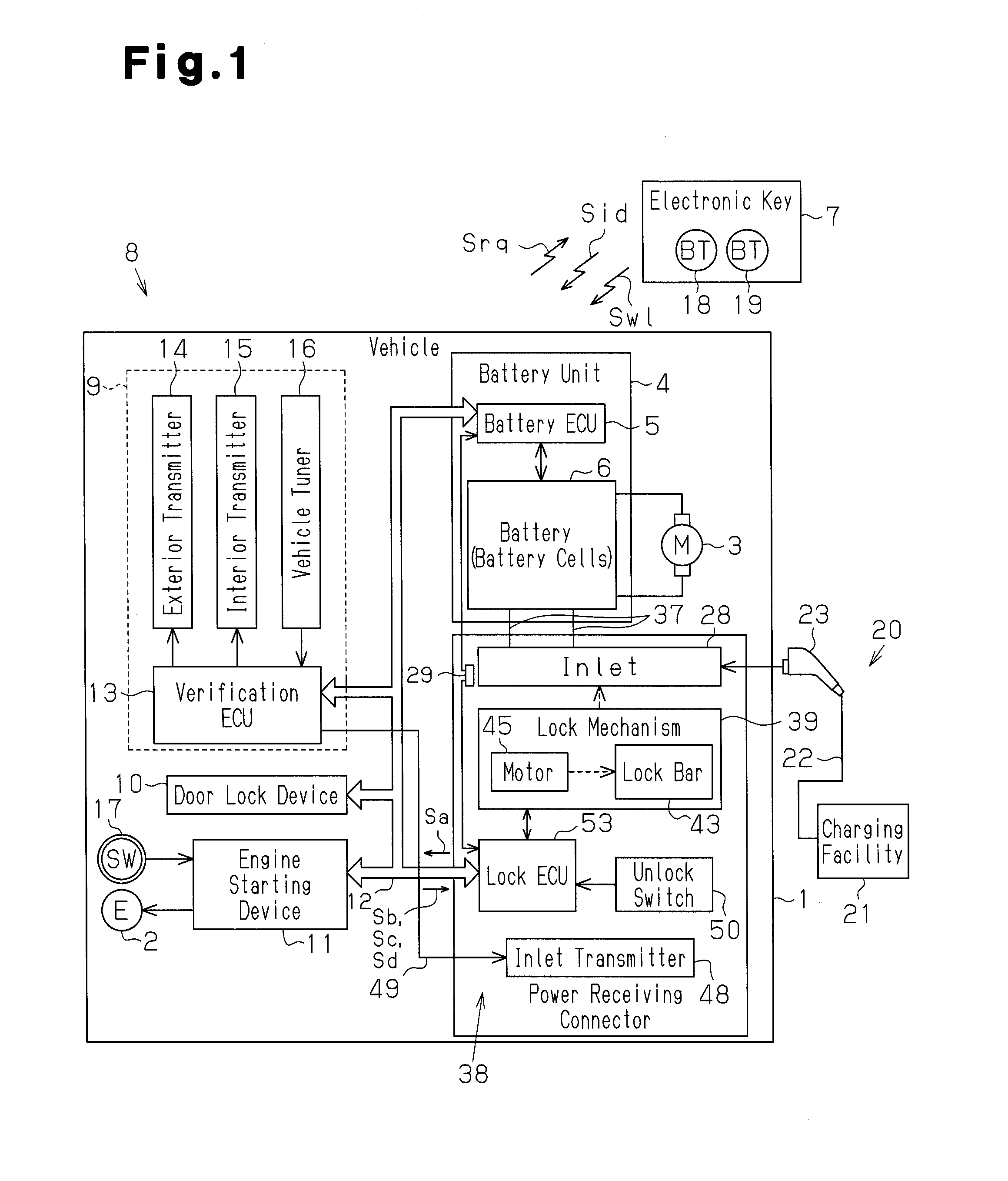
[0028]Referring to FIG. 1, a hybrid vehicle (hereinafter referred to as the vehicle 1) includes an engine 2 and a motor 3, which serve as power sources for vehicle wheels. The vehicle 1 is driven in one of a plurality of modes. More specifically, the vehicle 1 is operated in a mode using only the engine 2 to drive the wheels, a mode using the motor 3 while generating electric power with the engine 2 to drive the wheels, a mode using both the engine 2 and the motor 3 to drive the wheels, and a mode using only the motor 3 to drive the wheels. The vehicle 1 is one example of a communication device.

[0029]The vehicle 1 includes a battery unit 4 that supplies the motor 3 with power. The battery unit 4 includes a battery ECU 5, which manages operations of the battery unit 4, and a battery 6, which includes a plurality of battery cells. The battery unit 4 is a single unit, or battery pac...


PUM


Abstract

A locking device for a power feeding plug installed in a vehicle. The vehicle includes an inlet that receives the power feeding plug to charge a battery, which powers a motor. A door antenna transmits a verification signal to an electronic key. The locking device includes a lock bar moved between lock and unlock positions. The lock bar blocks the power feeding plug, which is attached to the inlet, when located at the lock position to prohibit removal of the power feeding plug from the inlet. An inlet antenna transmits the verification signal to an area that includes the inlet. The inlet antenna and door antenna are arranged at different locations. A controller moves the lock bar when verification of the electronic key is accomplished in response to the verification signal from the inlet antenna.

Description

CROSS-REFERENCE TO RELATED APPLICATIONS[0001]This application is based upon and claims the benefit of priority from prior Japanese Patent Application No. 2010-114416, filed on May 18, 2010, the entire contents of which are incorporated herein by reference.BACKGROUND OF THE INVENTION[0002]The present invention relates to a charging inlet device including a lock mechanism capable of locking a power feeding plug to a power receiving connector.[0003]Vehicles with reduced carbon dioxide emissions, such as hybrid vehicles and electric vehicles, have become popular in recent years. Such a vehicle uses a battery to power a motor, which produces rotation, and runs mainly using the drive force of the motor.[0004]Whenever the state of charge of the vehicle battery becomes low, the battery is charged, for example, with a household outlet or at a charging station. Japanese Laid-Open Patent Publication No. 9-161898 describes a power feeding plug connected to a distal end of a power cable. The pow...

Claims


Application Information

Patent Timeline
Patent Type & Authority Applications(United States)
IPC IPC(8): H01R13/62
CPCB60L11/1818B60L2270/32B60L2270/34H01R13/6275H01R13/6397Y02T90/16H01R2201/02H01R2201/26Y02T10/6269Y02T10/7005Y02T90/14H01R13/641Y04S30/14B60L53/16B60L53/65B60L53/68Y02T10/62Y02T10/7072Y02T90/12Y02T90/167Y02T10/70
Inventor KURUMIZAWA, NAOTOKAHARA, KEIJIKATAGIRI, TOSHIHARU
Owner KK TOKAI RIKA DENKI SEISAKUSHO
Why Eureka
Try Eureka