
Finger ring with size-accommodating inner liner

a technology of finger rings and inner lines, applied in the field of finger rings, can solve the problems of unresolved problems such as constant irritation, significant differences in finger diameter, and inability to properly size finger rings, and achieve the effect of improving comfort and structural integrity

Inactive Publication Date: 2011-12-01
BLUEROCK TECH
View PDF12 Cites 28 Cited by
  • Summary
  • Abstract
  • Description
  • Claims
  • Application Information

AI Technical Summary

Benefits of technology

[0007]In the present invention, a finger ring is provided which includes a size-accommodating inner liner formed substantially throughout of a pliable, flexible and resilient material. The inner liner is adhered to and extends at least partly around the inner diametrical surface of the outer substrate or band of a finger ring. Although it is preferred that the liner extend completely around the inner diametrical surface of the finger ring, with the improved comfort and structural integrity provided by the liner design, it is contemplated that the liner could extend only partly around and still provide the benefits described herein.
[0008]In one exemplary embodiment, the outer substrate of the ring may be formed of a substantially rigid material, comprising without limitation, a suitable metal or plastic material, or a combination of both. The inner liner may be formed throughout of a relatively flexible, pliable elastomeric material, such as silicone rubber, although it is also conceivable that the liner could be formed of other flexible plastics or thermoplastic elastomers, or a combination thereof, without departing from the invention herein. The liner is preferably constructed of a self-adhering material having a high resistance to the aggressive additives typically found in hand lotions, such as Stearic Acid and Glycol. The liner may then be overmolded to the inner surface of the outer ring substrate, thereby causing the liner to adhere to and extend peripherally around the inner diametrical surface thereof. The liner may also extend substantially across the entire axial width of the ring substrate to enhance the comfort of the ring, which will be described in more detail hereafter.
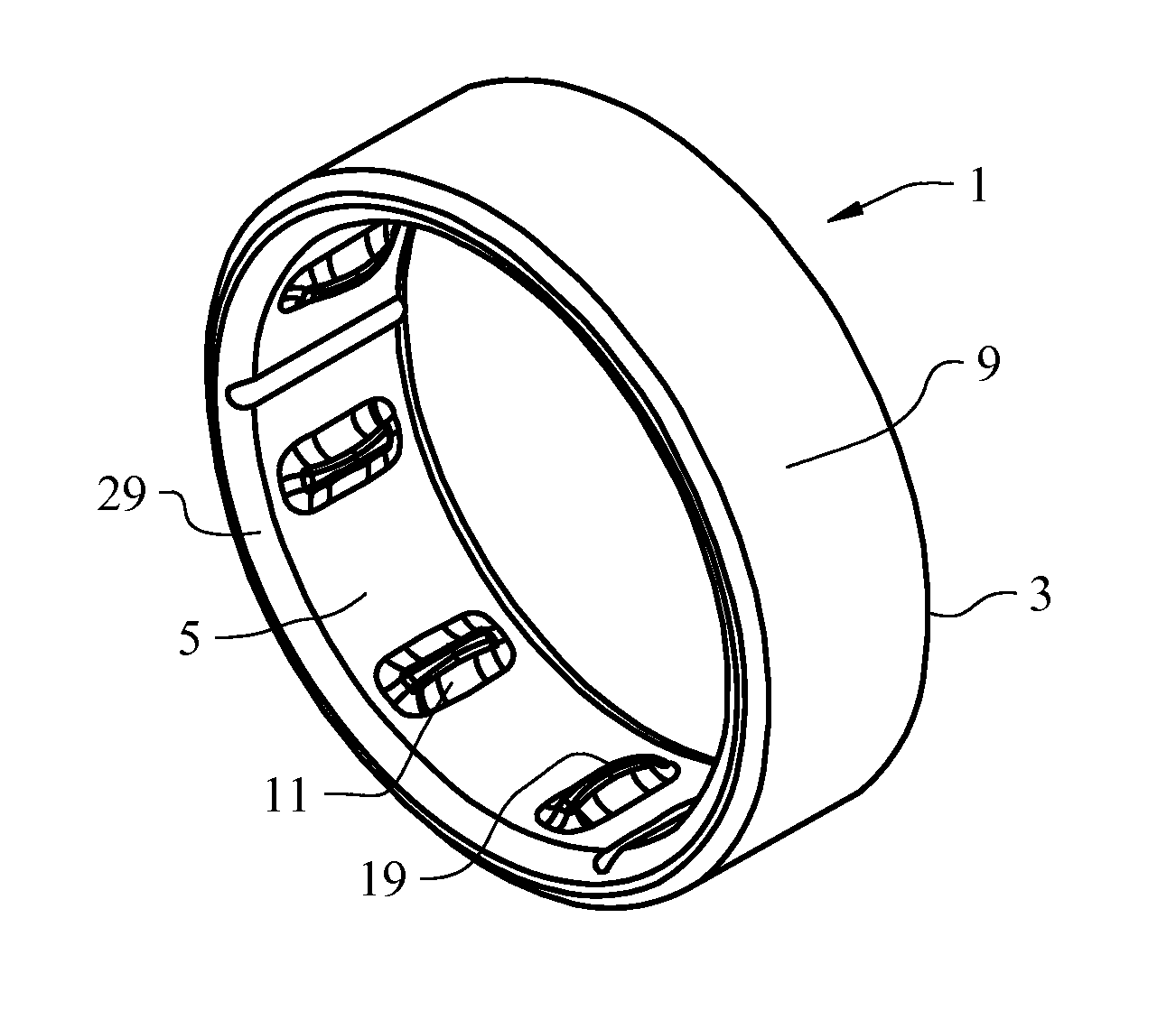
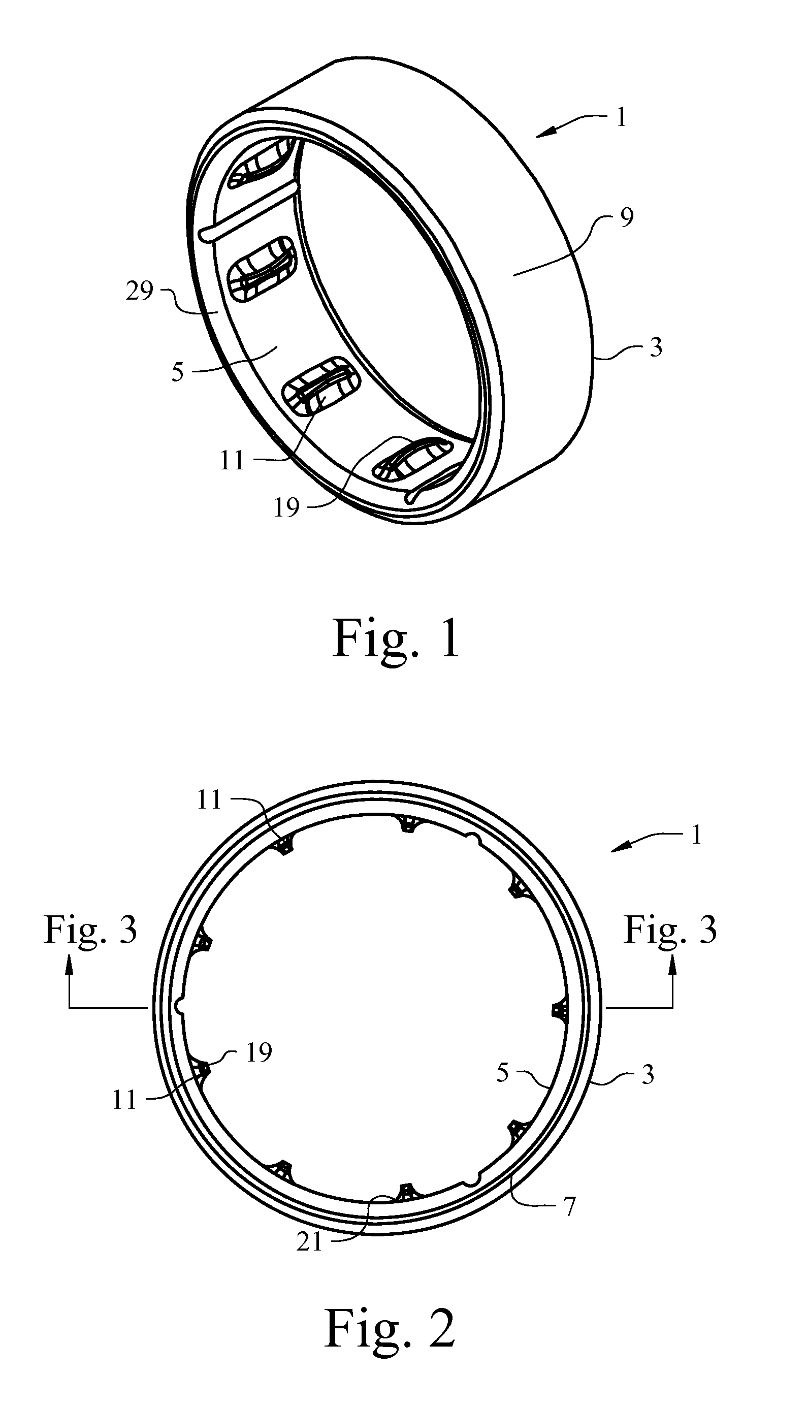
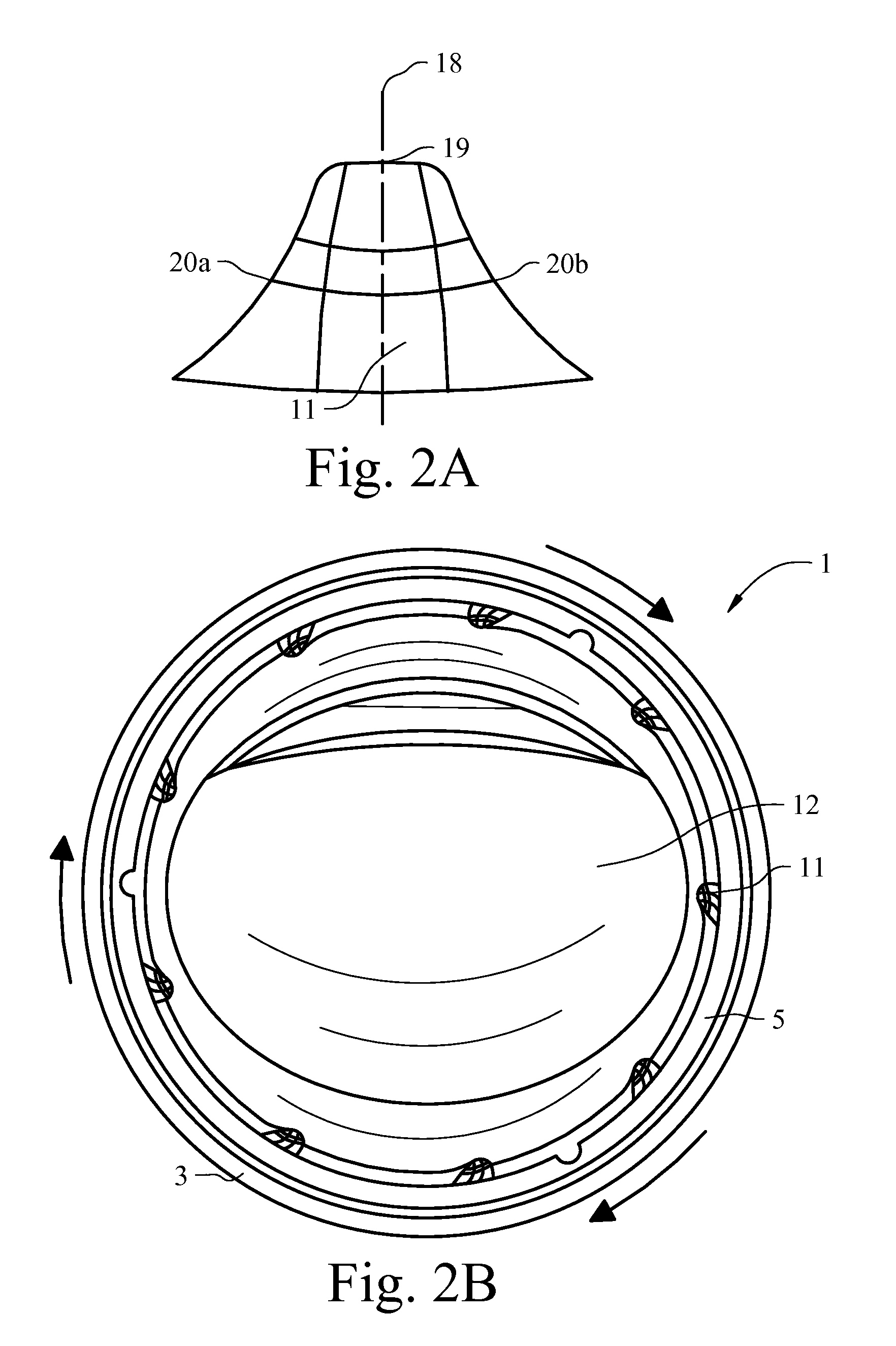
[0009]A plurality of peripherally spaced flexible ribs or protuberances are formed on the liner and extend radially inward therefrom to help facilitate ease of placement and removal of the ring from a person's finger, and to facilitate adjustment to and / or accommodation of variances in ring sizes. In one embodiment, each of the ribs extends generally longitudinally across at least a portion of the axial width of the liner. Each rib is constructed with a generally thin profile that tapers radially inwardly from the inner peripheral surface of the liner, thereby forming a plurality of flexible, resilient rib elements that are configured to readily fold or roll over upon rotation of the ring during placement or removal of the ring upon a finger. By folding over, the flexible ribs facilitate passage of the ring over the generally enlarged knuckle joint of the finger. After passing over the knuckle region, the ribs tend to relax to their original state. This prevents rotation and facilitates proper seating of the ring on the proximal phalanx of the finger; it also enhances the ability for the finger to breathe better underneath the ring.
[0010]In another exemplary embodiment, the inner diametrical surface of the outer ring substrate is configured with a liner retention shoulder formed adjacent at least one of the peripheral axial edges of the substrate for helping to retain the liner and resist the “shearing” forces subjected thereto upon transition of the ring on and off the finger. In one embodiment, a liner retention shoulder is formed adjacent each opposite peripheral edge portion of the outer ring substrate, thereby defining a central plateau that extends peripherally around the inner diametrical surface of the ring substrate. The liner then contours and adheres to the profile of the inner diametrical surface of the outer substrate of the ring in interengaging relation, so that much of the “shearing” forces imparted to the liner upon placement or removal of the ring upon the finger are directed into and absorbed by the shoulders formed in the ring substrate.
[0011]In still another exemplary embodiment, the outer diametrical surface of the ring substrate may be formed with one or more channel regions or depressions that form an aesthetically pleasing design of choice. These channels may then be configured to connect with one or more flow-through weep holes extending between the inner and outer diametrical surfaces of the ring substrate. This allows the liner material, while in its molten state during the overmolding process, to freely flow from one surface of the substrate to the other. Consequently, the molten liner material is permitted to flow into the channel regions in the outer surface of the ring substrate and adhere thereto to form an outer aesthetically pleasing design to the ring. Notably, once the liner material cures into a hardened state, the liner material extending through the weep holes to the outer surface of the ring will also function as an added retention member helping to secure the liner to the inner diametrical surface of the ring substrate and further prevent dislodgement therefrom.
[0012]Example embodiments are also provided herewith for methods for accommodating ring transition and ring fit on fingers of varying sizes. In one example embodiment, a method generally includes providing a ring with an inner diametrical liner having a plurality of flexible, resilient ribs or protuberances which tend to roll over upon rotation of the ring during placement or removal thereof from a finger. In another embodiment, the method generally includes providing an outer ring substrate with a liner retention shoulder that will help to absorb potential “shearing” forces and improve comfort upon placement or removal of the ring upon a finger.

Problems solved by technology

The ability to properly size a finger ring has been a longstanding unresolved problem.
For various reasons, the proximal interphalangeal joint (i.e., the “knuckle joint”) is oftentimes substantially enlarged relative to the finger phalanges it connects, thereby causing a significant disparity in finger diameter.
For typical finger rings of fixed diameter, this can be problematic in that the ring is either too tight to slide over the knuckle, or too loose on the proximal phalanx where the ring seats, resulting in constant irritation from undesirable persistent rotation of the ring on the finger.
However, the tape is unsightly, usually absorbs water and perspiration, and eventually wears out and becomes compressed through repeated passage over the knuckle.
Thus, frequent and time consuming replacement of the tape is required.
Such mechanical devices, however, are oftentimes uncomfortable and susceptible to breakage through repeated placement and removal of the ring upon the finger.
Such devices are typically mounted to the base of the ring, exerting pressure only to a localized region of the finger, which causes discomfort.
This, along with everyday wear and tear on the ring, eventually causes the device to shear or pull away from the inner ring surface to which it has been mounted.
Other sizing devices have been implemented which extend completely around the inner perimeter of a ring for better comfort, but have also proven to be susceptible to damage from transitional shearing forces and / or are complicated in design.
These aforementioned problems with finger rings have frustrated the jewelry industry for many years.
These large inventories are costly to maintain.

Method used


Image

  • Finger ring with size-accommodating inner liner
  • Finger ring with size-accommodating inner liner
  • Finger ring with size-accommodating inner liner

Examples


Embodiment Construction

[0023]With reference to FIGS. 1 and 2 of the drawings, a finger ring 1 is shown constructed in accordance with the present invention. Ring 1 is comprised generally of an outer annular substrate or band 3 to which an inner liner 5 is fixedly secured. As shown, liner 5 is adhered to the inner diametrical surface 7 of the outer substrate 3 offing 1, and extends around the entire inner periphery of substrate 3. While liner 5 extends completely around the inner periphery of substrate 3 in the embodiment shown, it is conceivable that liner 5 could extend only partly around substrate 3 without departing from the invention herein. For example, on a ring 1 having decorative indicia on a portion of the outer surface 9 of the ring substrate 3, it may be desirable for liner 5 to extend only along the inner base portion of substrate 3 opposite the decorative indicia. In the embodiment shown, liner 5 also extends completely across the axial width of substrate 3 for enhanced comfort to the wearer ...


PUM

PropertyMeasurementUnit
diameteraaaaaaaaaa
diameteraaaaaaaaaa
heightaaaaaaaaaa

Abstract

A finger ring is provided which includes a size-accommodating inner liner formed of a pliable, flexible and resilient material throughout and adhered to the inner diametrical surface of the ring. The liner includes a plurality of peripherally spaced flexible ribs extending inwardly therefrom to help facilitate ease of placement and removal of the ring from a person's finger, and to facilitate adjustment to and / or accommodation of variances in ring sizes. The outer substrate of the ring is formed with a liner retention shoulder to help retain the liner and resist shearing forces subjected thereto upon transition of the ring on and off the finger. The ring may be configured to permit simultaneous formation of aesthetically pleasing designs on the outer surface of the ring during the overmolding process utilized to form the inner liner therefor.

Description

CROSS REFERENCE TO RELATED APPLICATIONS[0001]This application claims the benefit of U.S. Provisional patent application No. 61 / 348,897, filed on May 27, 2010 by the same inventors, namely, Ted E. Ahrenholtz and Justin P. Boortz, and entitled “FINGER RING WITH SIZE-ACCOMODATING INNER LINER,”, the entire disclosure of which is incorporated herein by reference thereto.TECHNICAL FIELD[0002]The present invention relates generally to the field of finger rings, and more particularly to finger rings that are constructed to facilitate accommodation of multiple finger sizes and / or address sizing issues caused by aging, weight gain or loss, injury, arthritic conditions, etc.BACKGROUND OF THE INVENTION[0003]The ability to properly size a finger ring has been a longstanding unresolved problem. Human body types can vary widely. Although largely determined by genetics, the size and shape of a person's hands and fingers can change substantially over time as a result of aging, diet and other conditi...

Claims


Application Information

Patent Timeline
Patent Type & Authority Applications(United States)
IPC IPC(8): A44C9/02B23P13/00
CPCY10T29/21A44C9/02
Inventor AHRENHOLTZ, TED E.BOORTZ, JUSTIN PAUL
Owner BLUEROCK TECH
Learn More