

Sealing structure for wire lead-out hole
- Summary
- Abstract
- Description
- Claims
- Application Information
AI Technical Summary
Benefits of technology
Problems solved by technology
Method used
Image

Examples
first embodiment
[0040]The first embodiment is constructed as described above. Next, an operation of mounting the resilient seal 20 and the bracket 40 is briefly described.
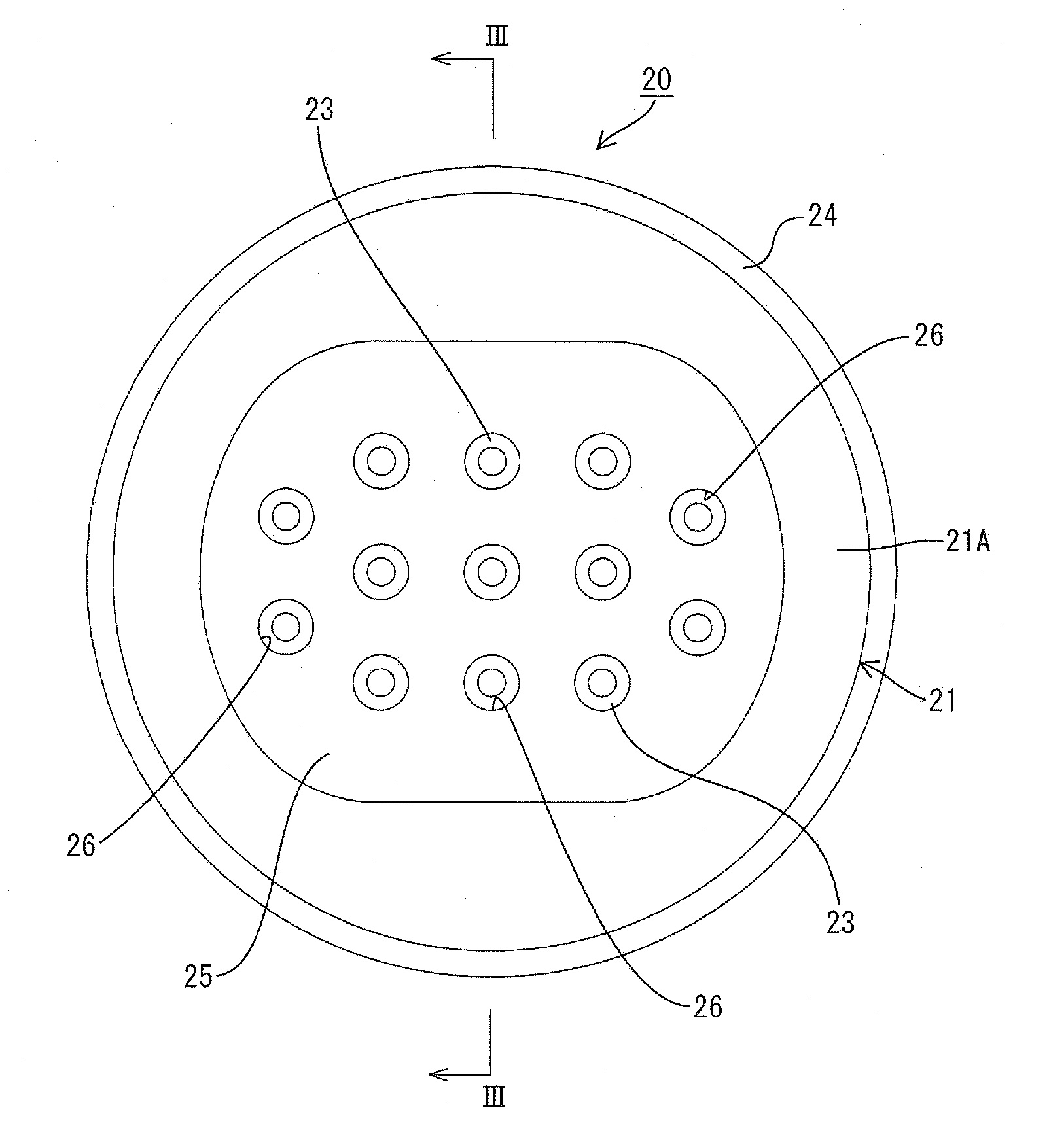
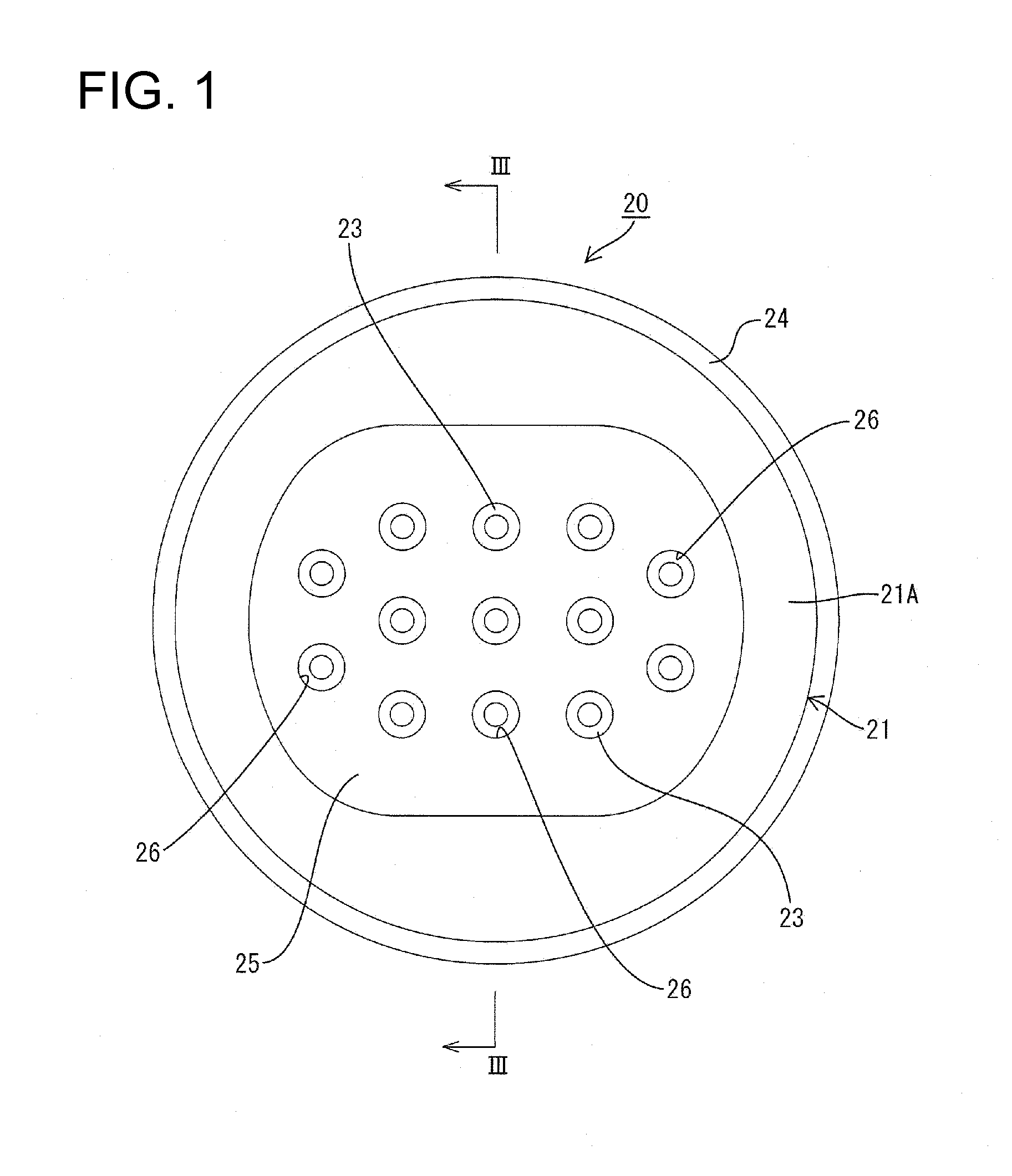
[0041]First, the wires Y are inserted into the wire insertion paths 26 from the wire protecting portion 25 of the resilient seal member 20 and further into the wire insertion holes 22. In this process, since the wire protecting portion 25 is formed with the wire insertion paths 26 for substantially guiding the wires Y to the wire insertion holes 22, the wires Y can be easily guided to the wire insertion holes 22, wherefore operability in inserting the wires Y can be improved. Further, since the respective wire insertion paths 26 particularly are independent in the wire protecting portion 25, entanglement of a plurality of wires Y can be prevented.
[0042]Further, the inner lip portions 23 of the wire insertion holes 22 are to be held in close contact with the outer peripheral surfaces of the wires Y to seal between the wires Y and t...
second embodiment
[0047]A wire protecting portion 25 of a resilient seal member 20 in the second embodiment is formed with a wire insertion recess 27 in an end surface 25A (projecting surface of the wire protecting portion 25) substantially opposite to a seal main body 21 as shown in FIG. 8. Thus, the peripheral wall of the wire insertion recess 27 is set to have such a thickness as to be substantially resiliently deformable. All wire insertion holes 22 of the seal main body 21 are open in a back wall 27A of the wire insertion recess 27, and the wire insertion recess 27 and all the wire insertion holes 22 communicate.
[0048]According to this construction, particularly material cost can be reduced by the volume of the wire insertion recess 27 upon forming the resilient seal member 20. In order to form long and narrow holes (wire insertion paths 26 in the first embodiment) continuous with the wire insertion holes 22 in the wire protecting portion 25, a mold needs to be formed with long and narrow shaft ...
third embodiment
[0050]In a wire protecting portion 25 of the third embodiment, slits 28 are formed in the peripheral wall of the wire protecting portion 25 as shown in FIGS. 9 and 10. These slits 28 are formed at or near four corners of the wire protecting portion 25 and / or substantially extend straight from an opening of a wire insertion recess 27 toward a seal main body 21.
[0051]According to this construction, in the case of inserting wires into wire insertion holes 22 from the wire insertion recess 27, an operator's hand can be inserted to the back of the wire insertion recess 27 by turning the peripheral wall of the wire protecting portion 25 outwardly. Thus, ends of wires Y can be more easily inserted into the wire insertion holes 22 and operability in mounting the wires Y can be improved.
[0052]The present invention is not limited to the above described and illustrated embodiments. For example, the following embodiments are also included in the technical scope of the present invention as defin...
PUM
 Abstract
Description
Claims
Application Information