Method for transmitting an image from a first control unit to a second control unit and output unit

a technology of output unit and control unit, which is applied in the direction of instruments, computing, electric digital data processing, etc., can solve the problems of time-consuming manner

Inactive Publication Date: 2011-12-01
SIEMENS AG
View PDF13 Cites 8 Cited by
  • Summary
  • Abstract
  • Description
  • Claims
  • Application Information

AI Technical Summary

Benefits of technology

[0022]The interface element—developed for viewing the document or the image and for inserting annotations—on the first output unit has precisely the resolution or size (in pixels) of the interface element developed for the display in the HMD. This prevents otherwise necessary scaling operations, in which the document is sometimes visually impaired. From the general stock of documents, the expert in the back office selects documents and determines the required document section for each work step by the engineer, sometimes even a plurality of sections per document. The expert adds any annotations and stores them in a structured directory which is made available to the engineer online or offline.

Problems solved by technology

To date, the maintenance engineer has used a zoom function to select the important details from the documents, in a time-consuming manner.

Method used


Image

  • Method for transmitting an image from a first control unit to a second control unit and output unit
  • Method for transmitting an image from a first control unit to a second control unit and output unit
  • Method for transmitting an image from a first control unit to a second control unit and output unit

Examples


Embodiment Construction

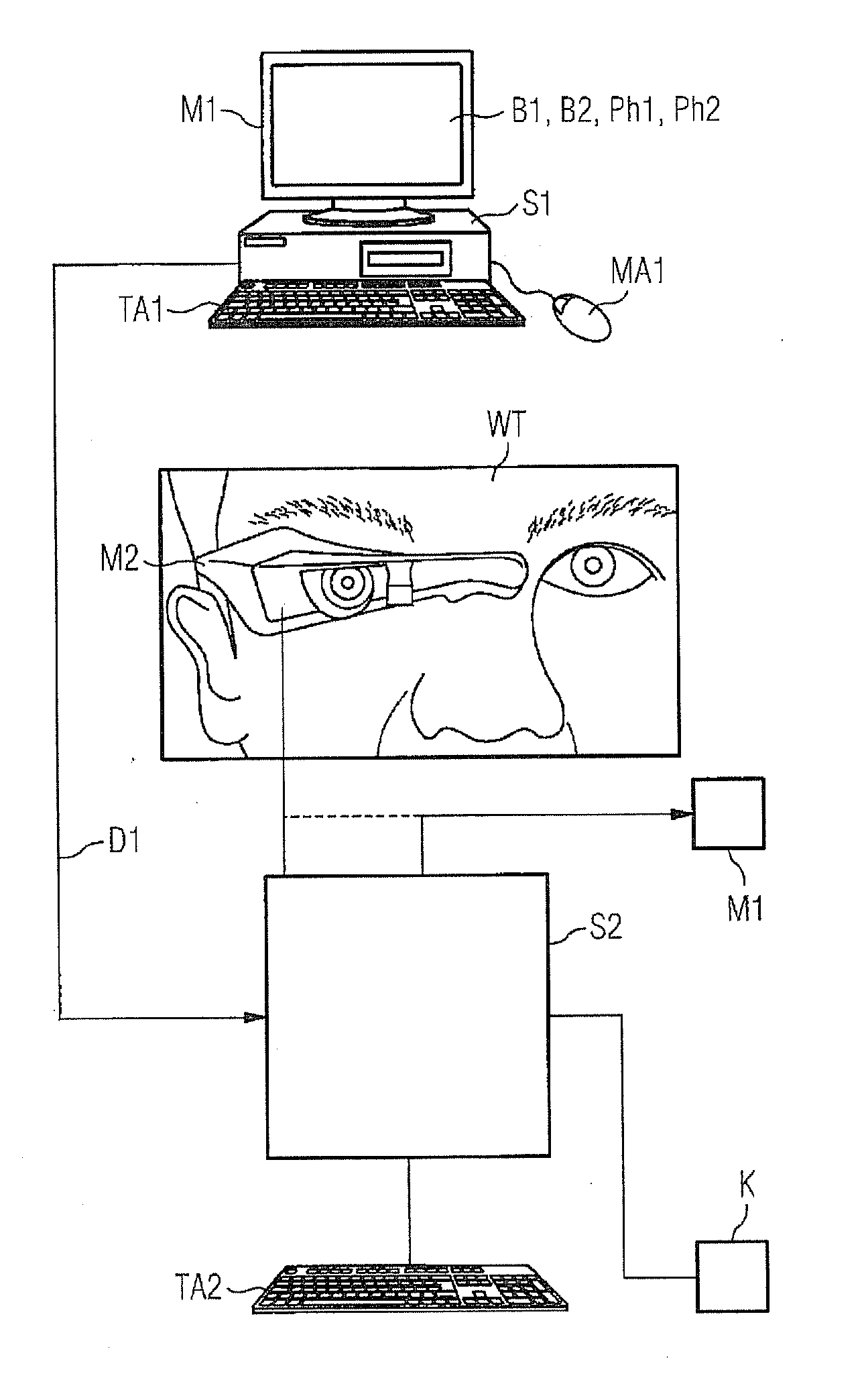
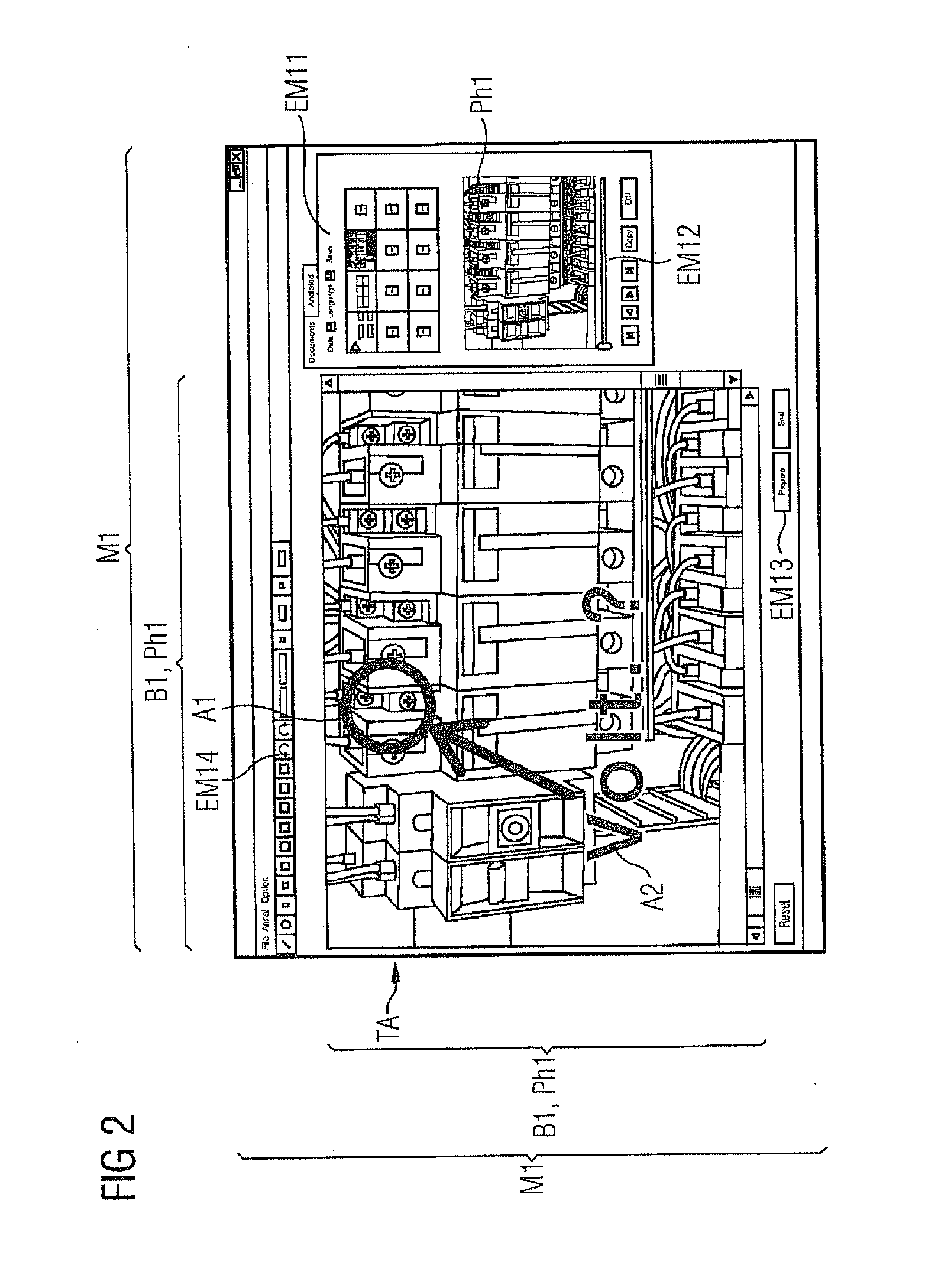
[0029]FIG. 1 shows the system on which the method for transmitting an image from a first to a second control unit S1, S2 is executed. FIG. 1 shows a first control unit S1, which is a commercially available computer. As an input medium, the control unit S1 has a keyboard TA1 and a mouse MA connected to it. The output unit M1 is in the form of a commercially available LCD monitor having a high image resolution of 1280×800 or more. The monitor M1 is used to output the images B1, B2, photographs PH1, PH2 and input panels EM11 to EM14 which are shown in the subsequent figures.

[0030]A second control unit S2 is provided, to which a keyboard TA2, a mouse MA2, a microphone MI and a second output unit M2 can be connected as input media. The second output unit M2 is in the form of a head-mounted display (HMD) which is worn on the head by a maintenance engineer WT and allows flexible mobile use even under difficult ambient conditions.

[0031]It is also possible for the second control unit S2 to h...


PUM


Abstract

A method for transmitting an image from a first control unit to a second control unit is provided wherein a maintenance technician can view the same image on a head-mounted display from the first output unit as an expert in the back office. The image is played back on the first output unit with the same resolution as on the head-mounted display.

Description

CROSS REFERENCE TO RELATED APPLICATIONS[0001]This application is the US National Stage of International Application No. PCT / EP2009 / 061959, filed Sep. 15, 2009 and claims the benefit thereof. The International Application claims the benefits of German application No. 10 2008 061 448.3 DE filed Dec. 10, 2008. All of the applications are incorporated by reference herein in their entirety.FIELD OF INVENTION[0002]The invention relates to a method for transmitting an image from a first control unit to a second control unit, and an output unit for carrying out the method.BACKGROUND OF INVENTION[0003]Wikipedia “Head-Mounted Display” (printed March 2009) discloses various embodiments of a head-mounted visual output appliance which shows images produced on the computer on a screen close to the eye or projects them directly onto the retina.[0004]For the purpose of maintaining technical installations, the maintenance engineer has a mobile computer system having a head-mounted display HMD. The m...

Claims


Application Information

Patent Timeline
Patent Type & Authority Applications(United States)
IPC IPC(8): G09G5/00
CPCG02B27/017G06F3/012G02B2027/0187G02B2027/014
Inventor ARNDT, FRANKBRUMMEL, HANS-GERDHEBLINSKI, VOLKERPASCHMANN, WILLIREIMANN, CHRISTIANSANTELMANN, HOLGERSCHMIDT, OLAFSCHULZ, GERHARDWEBER, DIETMAR
Owner SIEMENS AG
Why Eureka
Try Eureka