Direct-current power supply device
a power supply device and direct current technology, applied in the field of direct current power supply devices, can solve the problems of poor power factor and badly affecting surrounding areas
- Summary
- Abstract
- Description
- Claims
- Application Information
AI Technical Summary
Benefits of technology
Problems solved by technology
Method used
Image
Examples
first embodiment
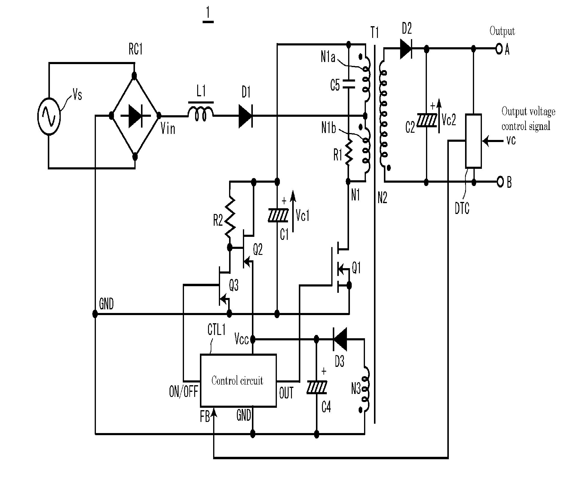
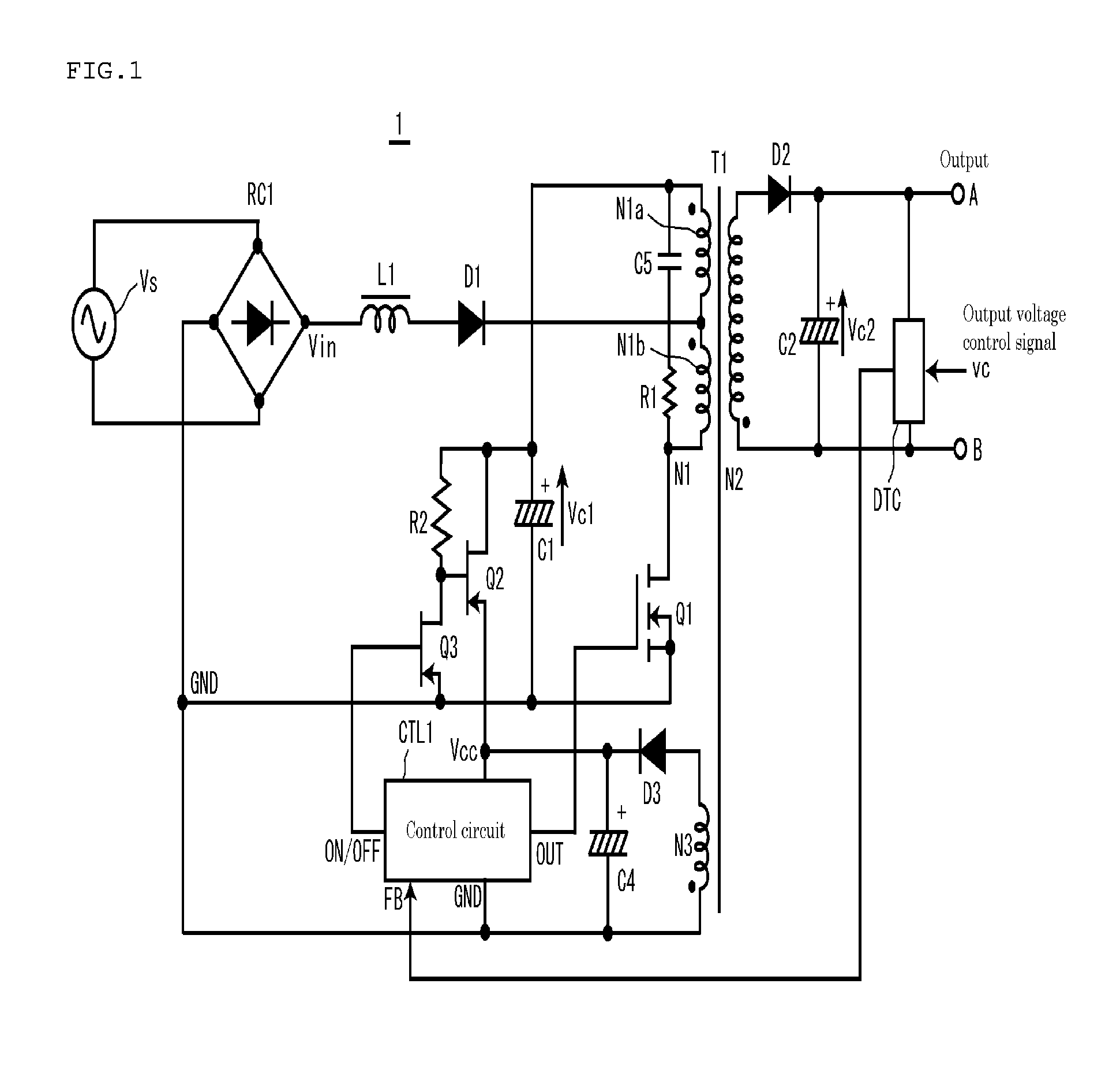
[0057]FIG. 1 shows the circuit configuration of a direct-current power supply device 1 of the first embodiment of the present invention. The direct-current power supply device 1 is different from the direct-current power supply device 100 of the conventional technique shown in FIG. 7 in that a circuit (switching elements Q2 and Q3, and resistance R2) for supplying electric charge of a smoothing capacitor C1 to power supply Vcc of a control circuit CTL1 is provided, with the switching elements Q2 and Q3 controlled by an ON / OFF signal from the control circuit CTL1 at a time when a load is light. The switching elements Q2 and Q3 and the resistance R2 make up a circuit that also serves as a start-up circuit of a control circuit. Incidentally, an auxiliary winding N3 of a transformer T1, a diode D3, a smoothing capacitor C4 and the like are not shown in FIG. 7 but are shown in FIG. 1. The bypass capacitor C3, which is shown in FIG. 7 but not in FIG. 1, a high frequency component removing...
second embodiment
[0065]FIG. 3 shows the circuit configuration of the direct-current power supply device 2 of the second embodiment of the present invention. The direct-current power supply device 2 is different from the direct-current power supply device 1 of the first embodiment shown in FIG. 1: while the drain terminal of the switching element Q2 is connected to one terminal (positive-electrode terminal) of the smoothing capacitor C1 in the direct-current power supply device 1, the drain terminal of the switching element Q2 is connected to a connection point where the other terminal of the second primary winding N1b of the transformer T1 and the drain terminal of the switching element Q1 are connected together in the direct-current power supply device 2. The configuration of the other parts is the same as that of the first embodiment and therefore will not be described in detail.
[0066]According to the present second embodiment, unlike the first embodiment, the energy accumulated in the smoothing c...
third embodiment
[0068]FIG. 4 shows the circuit configuration of the direct-current power supply device 3 of the third embodiment of the present invention. In the direct-current power supply device 3, the switching elements Q2 and Q3 and resistance R2, which the direct-current power supply devices of the first and second embodiments include, are removed. Instead of the reactor L1, a reactor L2 including a main winding P and an auxiliary winding S is provided. The main winding P is used in the same way as the reactor L1 of the first or second embodiment. Part of the magnetic energy of the reactor L2 is supplied to the power supply Vcc of a control circuit CTL3 from the auxiliary winding S via a diode D4 at a time when the load is light. The configuration of the other parts is the same as that of the first or second embodiment and therefore will not be described in detail.
[0069]When the load is heavy, as in the case of a circuit of a conventional technique, the power supply Vcc of the control circuit ...
PUM
 Abstract
Description
Claims
Application Information
 - R&D
- Intellectual Property
- Life Sciences
- Materials
- Tech Scout
- Unparalleled Data Quality
- Higher Quality Content
- 60% Fewer Hallucinations
Browse by: Latest US Patents, China's latest patents, Technical Efficacy Thesaurus, Application Domain, Technology Topic, Popular Technical Reports.
© 2025 PatSnap. All rights reserved.Legal|Privacy policy|Modern Slavery Act Transparency Statement|Sitemap|About US| Contact US: help@patsnap.com


