
Shrink disk connection for a wind turbine

a wind turbine and shrink disk technology, applied in the direction of cables, vehicles/pulleys, bearings, etc., can solve the problems of difficult to separate the shafts from each other, difficult or time-consuming to connect and lock the shafts to each other, and inability to withstand the torque provided, so as to achieve a solution. , the effect of reducing the number of times

Inactive Publication Date: 2011-12-01
VESTAS WIND SYST AS
View PDF7 Cites 9 Cited by
  • Summary
  • Abstract
  • Description
  • Claims
  • Application Information

AI Technical Summary

Benefits of technology

[0005]It may be seen as an object of the present invention to provide an improved wind turbine shaft connection, an improved method of connecting a first shaft with a second shaft in a wind turbine and a wind turbine including such a shaft connection. Preferably, the invention alleviates, mitigates or eliminates one or more of the above or other disadvantages singly or in any combination.
[0006]In particular, it may be seen as an object of the invention to provide a solution which is found to be able to withstand the torque and possibly also bending moments provided between a main shaft in a wind turbine and another shaft while still being relatively inexpensive and possibly also simple and effective to use.

Problems solved by technology

Examples of disadvantages with some solutions are that it has proved difficult or time consuming to connect and lock the shafts to each other and possibly also difficult to separate the shafts from each other again.
Other solutions have proven that they were not able to withstand the torque provided and yet some solutions have additionally or alternatively proven to be too expensive or relatively large when considering their overall effectiveness.

Method used


Image

  • Shrink disk connection for a wind turbine
  • Shrink disk connection for a wind turbine
  • Shrink disk connection for a wind turbine

Examples


Embodiment Construction

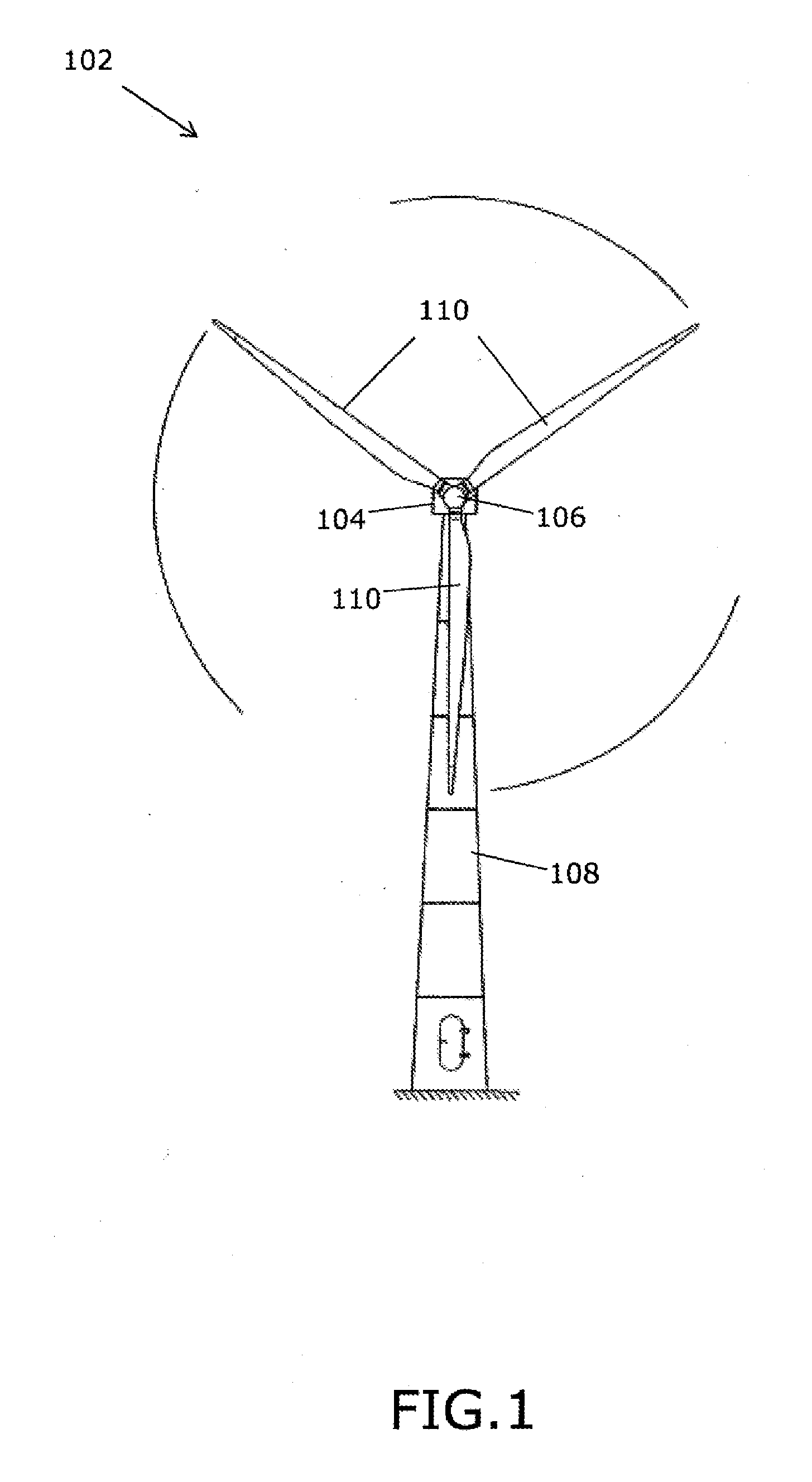
[0051]FIG. 1 shows a wind turbine 102 with a nacelle 104, and a hub 106 rotatable mounted to the nacelle 104 via a first shaft. In this example the first shaft is the main shaft of the wind turbine (not shown in FIG. 1). The nacelle 104 is rotatable mounted on a wind turbine tower 108. The hub 106 of the wind turbine includes three wind turbine blades 110 which rotate around a first shaft centre axis of the wind turbine in a rotational plane substantially perpendicular to the first shaft centre axis.

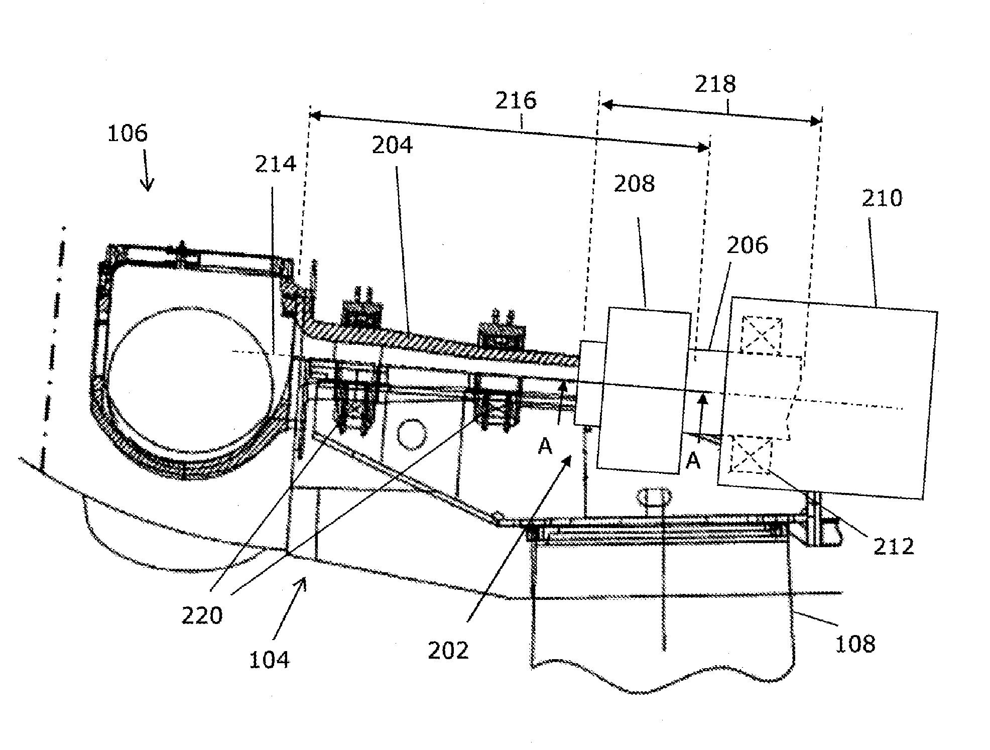
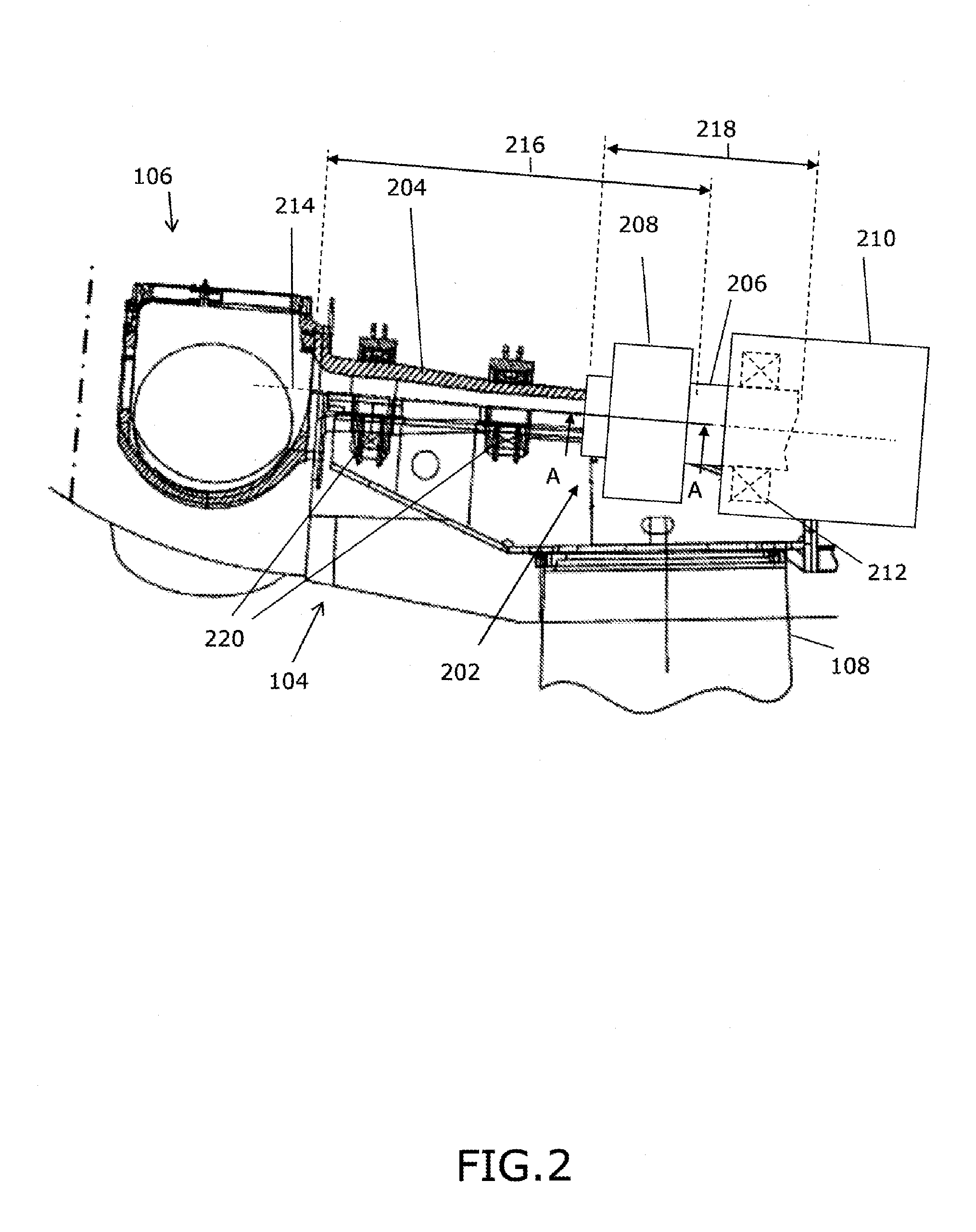
[0052]FIG. 2 is a side view of the hub 106 and the nacelle 104. Some parts, such as the first shaft 204, comprised in the hub and in the nacelle are shown in a cross-sectional view. The figure shows the first shaft centre axis 214 running in a longitudinal direction in a centre of the first shaft 204.

[0053]In particular, the figure shows a connection 202 for or in a wind turbine, with a first shaft 204 with a length 216 in a longitudinal direction and a first shaft end with a radial exte...


PUM

PropertyMeasurementUnit
lengthaaaaaaaaaa
pressureaaaaaaaaaa
frictionaaaaaaaaaa

Abstract

In order e.g. to provide a connection for connecting shafts in a wind turbine which is able to withstand a torque of a modern wind turbine, while still being relatively inexpensive, simple and effective to use, there is disclosed a connection including a first shaft and a second shaft which are inter-connectable by connecting an interconnection part of the first shaft and an interconnection part of the second shaft, and a shrinkable disk positioned and adapted so as to lock the first shaft to the second shaft by providing pressure to the interconnection parts of the first and second shaft when the interconnection parts are interconnected, and where the interconnection part of each of the first and second shafts comprises a plurality of friction surfaces transferring moment between the first and second shafts by friction.

Description

FIELD OF THE INVENTION[0001]The invention relates to a rigid shrink disk connection for a wind turbine. The connection is provided by inter-connectable members and a shrinkable disk.BACKGROUND OF THE INVENTION[0002]Wind turbines are used to gather wind energy and to transform the energy into another form of energy. For this purpose most wind turbines includes a main shaft which in one end is coupled to blades of the wind turbine. The main shaft is in the opposite end normally connected to another shaft or shaft like member of the wind turbine. This other shaft may be a shaft such as an entrance shaft or member of a gearbox or an entrance shaft or torque transferring member of an electric energy generator.[0003]In modern wind turbines, a torque which is to be transferred between the main shaft and another member or shaft is relatively high, such as lying in the interval between 3000 and 7500 kilo Newton meters.[0004]Various solutions have been provided in wind turbines in order to tr...

Claims


Application Information

Patent Timeline
Patent Type & Authority Applications(United States)
IPC IPC(8): F03D11/02B23P11/02
CPCY10T403/48Y10T29/49863F05B2240/50F05B2260/403F05B2240/60Y10T403/40F05B2260/40F05D2260/403F05D2240/50Y02E10/722F16D1/02F02C7/36Y10T403/7039F05D2260/40F16D1/0858F05D2240/60F16D1/04F05D2240/61Y10T403/551F03D11/02F05B2240/61Y10T403/21F03D15/00F16B2200/10F03D80/70Y02E10/72
Inventor RIISAGER, PETER ALAEKOLSEN, NIELS CHRISTIAN
Owner VESTAS WIND SYST AS
Learn More