Apparatus for lidding or delidding microplate

Inactive Publication Date: 2011-12-01
HIGHRES BIOSOLUTIONS INC
View PDF2 Cites 29 Cited by
  • Summary
  • Abstract
  • Description
  • Claims
  • Application Information

AI Technical Summary

Problems solved by technology

As a first shortcoming, it has been found to be rather difficult to adhere a secondary foil layer on a microplate after the primary foil layer has been removed or pierced, thereby precluding reuse of the microplate, which is highly undesirable.
As a second shortcoming, it has been found to be rather difficult to determine the exact location of an individual well in a high density microplate (e.g., microplates with at least 1536 wells) through the foil seal.
Accordingly, prior to locating the selected well using the foil piercing instrument, a laboratory technician o

Method used


Image

  • Apparatus for lidding or delidding microplate
  • Apparatus for lidding or delidding microplate
  • Apparatus for lidding or delidding microplate

Examples


first embodiment

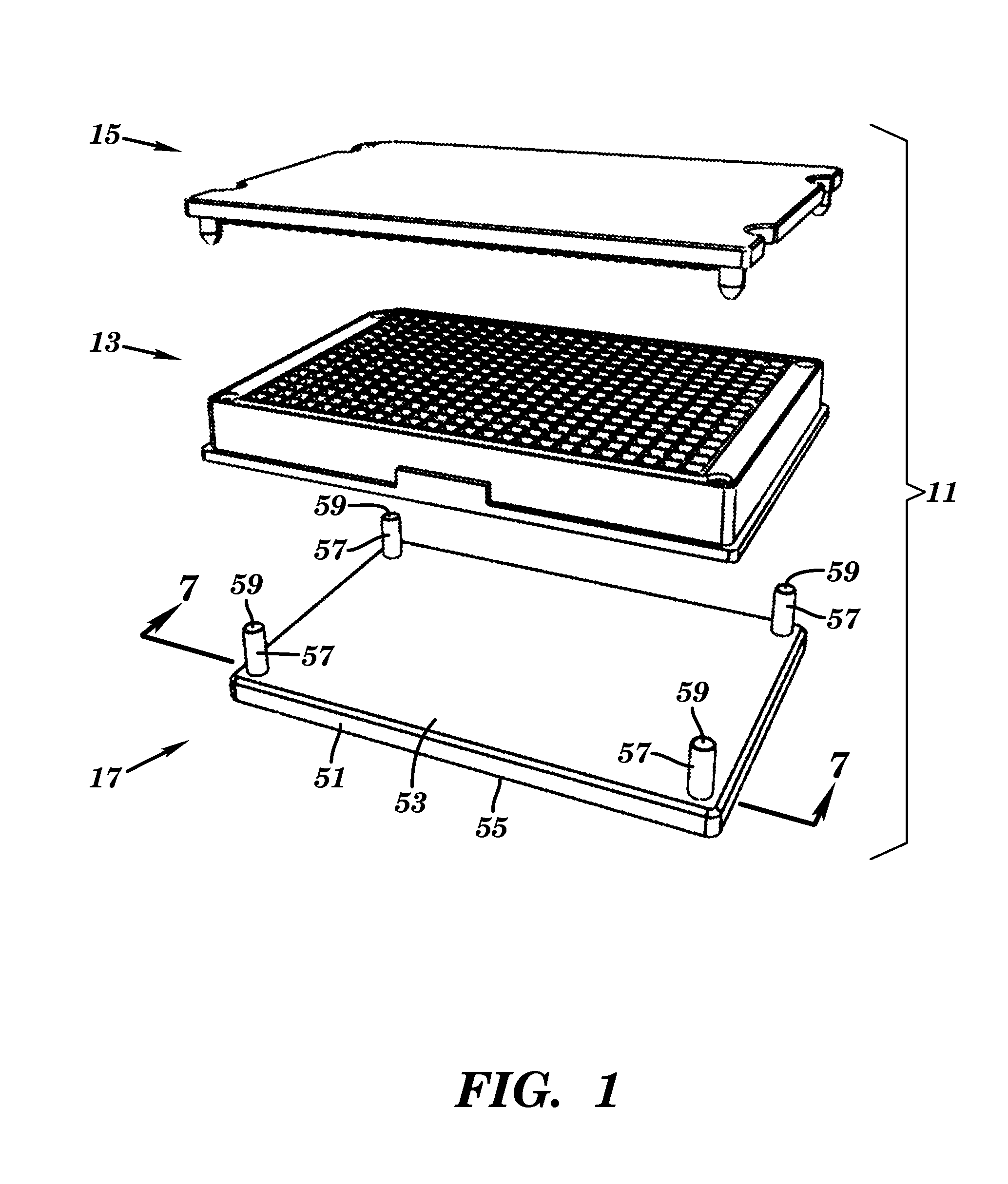
[0033]Referring now to FIG. 1, there is shown an exploded, top perspective view of a microplate kit that is constructed according to the teachings of the present invention and identified generally by reference numeral 11.

[0034]Microplate kit 11 comprises a microplate 13, a lid 15 and a lid removal tool 17. As will be described in detail below, lid 15 is designed to be mounted on microplate 13. Tool 17 is designed to assist in the removal (i.e., or delidding) of lid 15 when mounted on microplate 13.

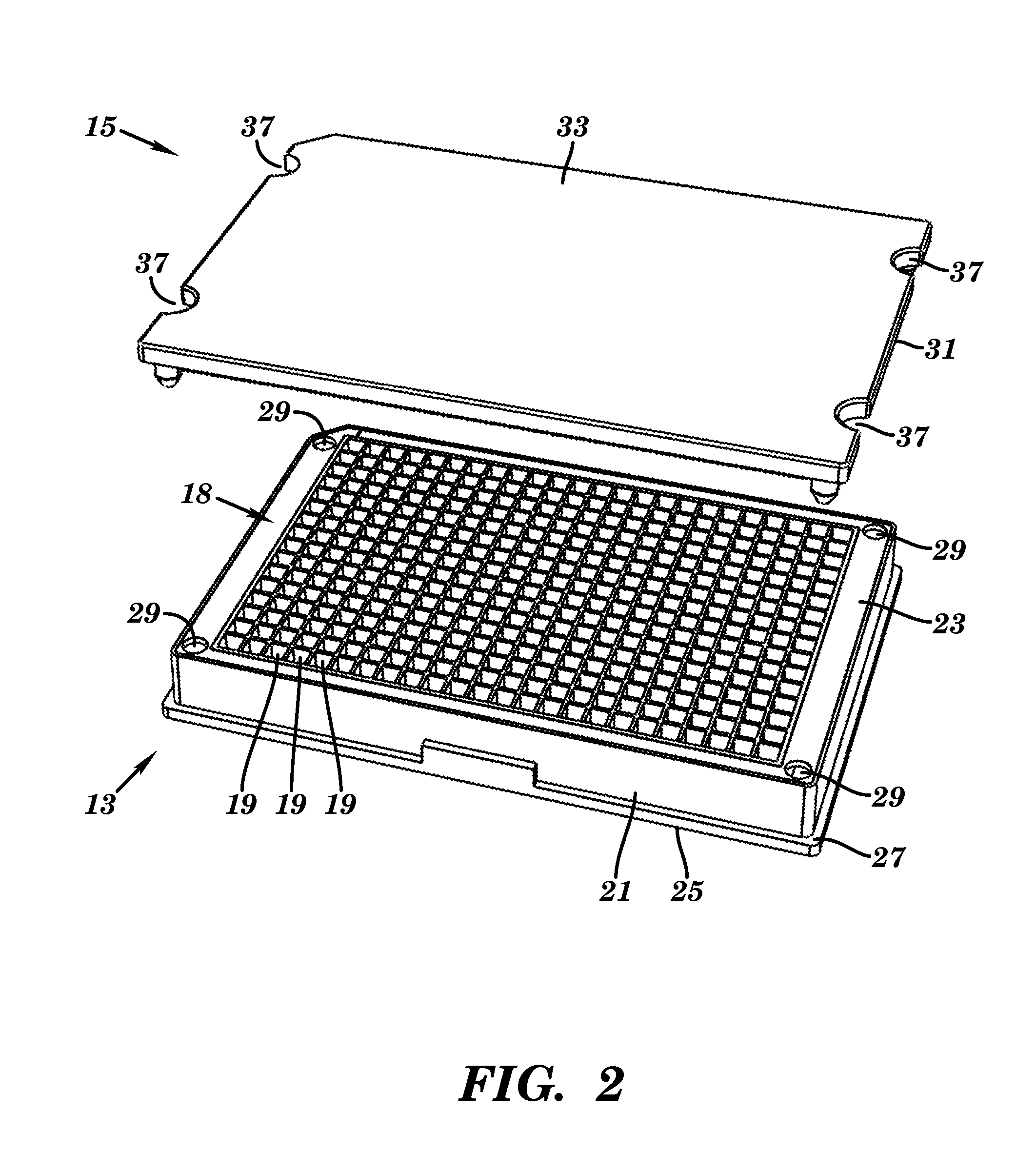
[0035]Referring now to FIG. 2, microplate 13 has a generally block-shaped design and includes an enlarged sample area 18 that is provided with a plurality of individual, vertically-disposed wells 19. In the present embodiment, microplate 13 is represented as having 384 wells. However, it is to be understood that the present invention is not limited to any particular density of wells 19. Rather, the number of wells 19 could be modified to any density without departing from the spirit of the...

second embodiment

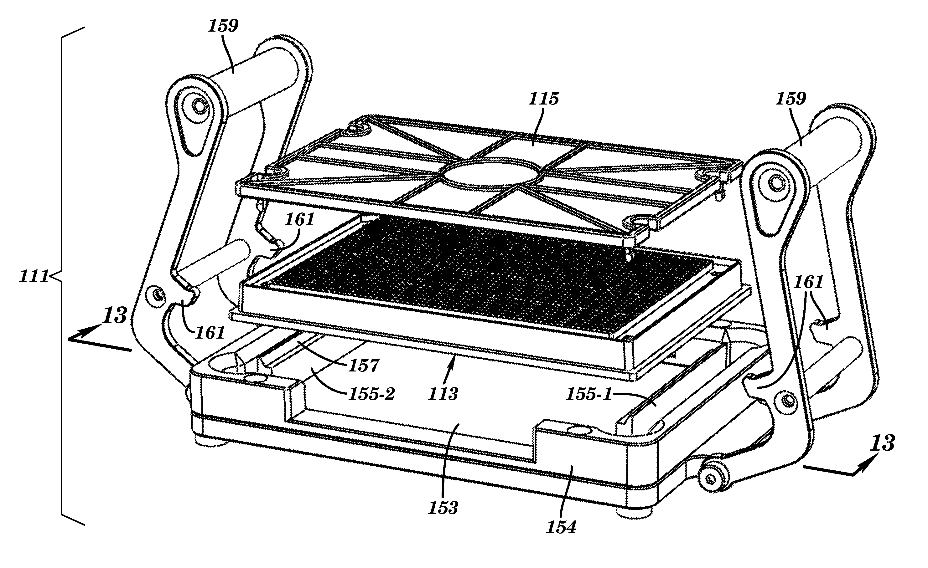
[0056]Referring now to FIG. 8, there is shown an exploded, top perspective view of a microplate kit that is constructed according to the teachings of the present invention and identified generally by reference numeral 111.

[0057]Microplate kit 111 is similar to microplate kit 11 in that microplate kit 111 comprises a microplate 113, a lid 115 designed to be removably mounted onto microplate 113 and a tool 117 designed to assist in the removal of lid 115 when mounted on microplate 113.

[0058]Referring now to FIG. 9, microplate 113 is similar to microplate 13 in that microplate 113 is generally block-shaped in its design and includes an enlarged sample area 118 that is provided with a plurality of individual, vertically-disposed wells 119. Microplate 113 similarly includes a hollow outer frame, or sidewall, 121 that is formed directly around the periphery of sample area 118, sidewall 121 having an inverted U-shaped configuration in lateral cross-section (as seen most clearly in FIG. 12(...


PUM

PropertyMeasurementUnit
Areaaaaaaaaaaa

Abstract

An automated lidder and/or delidder apparatus to engage and disengage a lid from a microplate is disclosed. The microplate includes a sample area with a plurality of individual wells and a hollow outer frame formed around the sample area, the frame being shaped to include a plurality of openings in its top surface. The lid includes a plate and a plurality of latches formed on the underside of the plate. In the lidding process, the apparatus presses down on the lid to insert each latch through a corresponding opening in the microplate until the latch snaps into engagement with the frame. In the delidding process, the apparatus inserts delidding posts into the openings to disengage the latches from the frame.

Description

CROSS-REFERENCE TO RELATED APPLICATIONS[0001]The present application is a continuation-in-part of U.S. application Ser. No. 12 / 008,829, filed Jan. 14, 2008, currently pending, which claims the benefit under 35 U.S.C. 119(e) of U.S. Provisional Patent Application Ser. No. 60 / 880,173, filed on Jan. 12, 2007, both of which are incorporated by reference herein.BACKGROUND OF THE INVENTION[0002]The present invention relates generally to microplates that are typically used in the life sciences industry and more particularly to an apparatus for lidding and / or delidding microplates.[0003]In the areas of biological, chemical and pharmaceutical research, it is a common practice to utilize microplates for storage and analytical purposes. Microplates (also commonly referred to in the art as multi-well plates, specimen plates and microtitre plates) have a block-shaped design and include a plurality of wells (e.g., 1, 2, 4, 6, 12, 24, 48, 96, 384, 1536, etc.) in its top surface, each well serving ...

Claims


Application Information

Patent Timeline
IPC IPC(8): B01L3/00
CPCB01L3/50853B01L9/523B01L2200/025B01L2200/0689B01L2200/18Y10T29/49998B01L2300/0829G01N2035/0405Y10T29/53991Y10T29/49769B01L2300/041
Inventor NICHOLS, MICHAEL J.GUARRACINA, LOUIS J.
Owner HIGHRES BIOSOLUTIONS INC
Why Eureka
Try Eureka