Method for Controlling a Gas Burner and a Hob with Several Gas Burners

Inactive Publication Date: 2011-12-01
E G O ELEKTRO GERAETEBAU GMBH
View PDF12 Cites 5 Cited by
  • Summary
  • Abstract
  • Description
  • Claims
  • Application Information

AI Technical Summary

Benefits of technology

Furthermore, operation by the person can be very greatly simplified when, for example, he sets a required power at only one operating element of one of the two gas burners and when both gas burners are operated with the same power thanks to the adjustment of the power ranges. The other operating element of the other

Problems solved by technology

These valves can however only be completely shut or completely opened.
Below this

Method used


Image

  • Method for Controlling a Gas Burner and a Hob with Several Gas Burners
  • Method for Controlling a Gas Burner and a Hob with Several Gas Burners
  • Method for Controlling a Gas Burner and a Hob with Several Gas Burners

Examples


Embodiment Construction

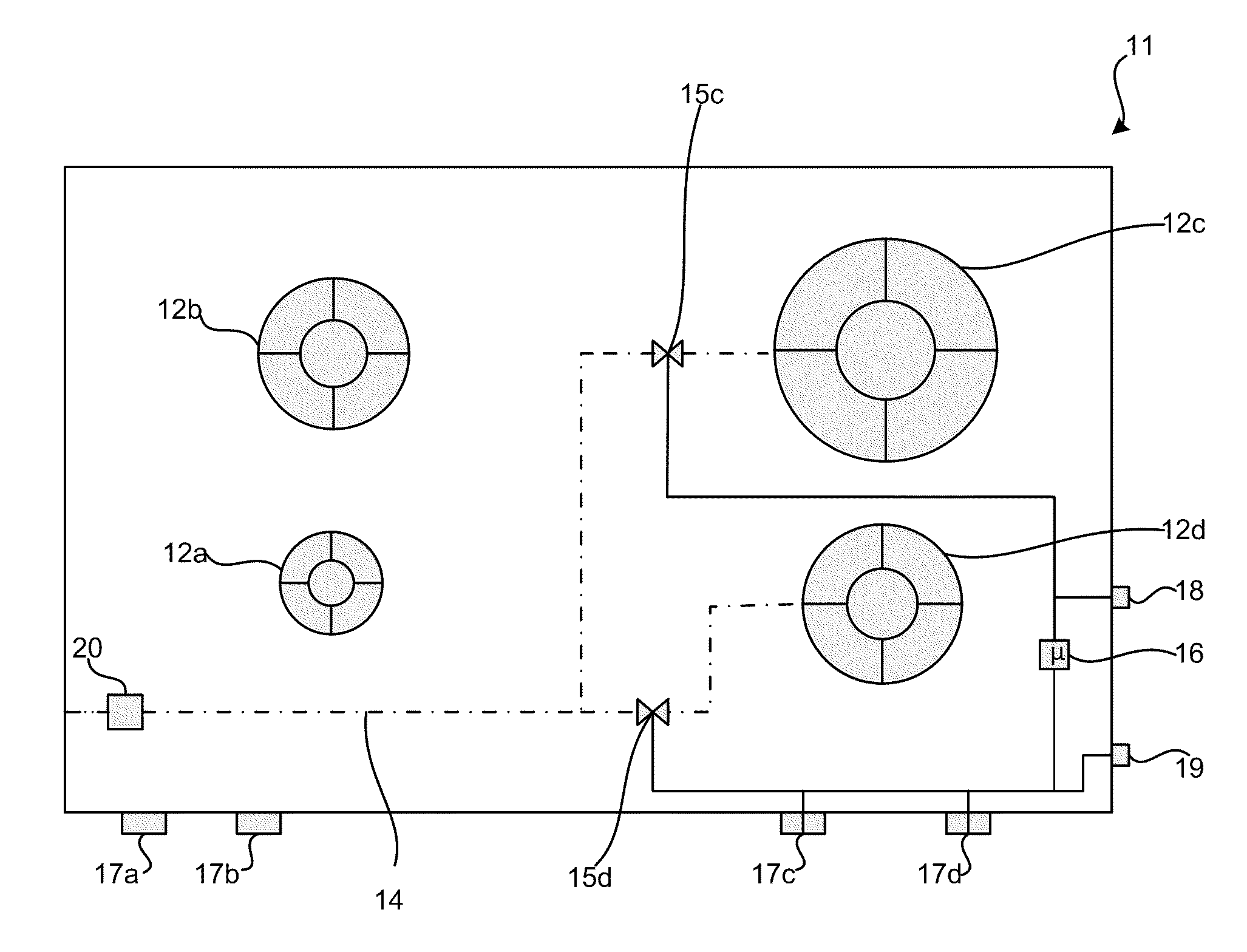
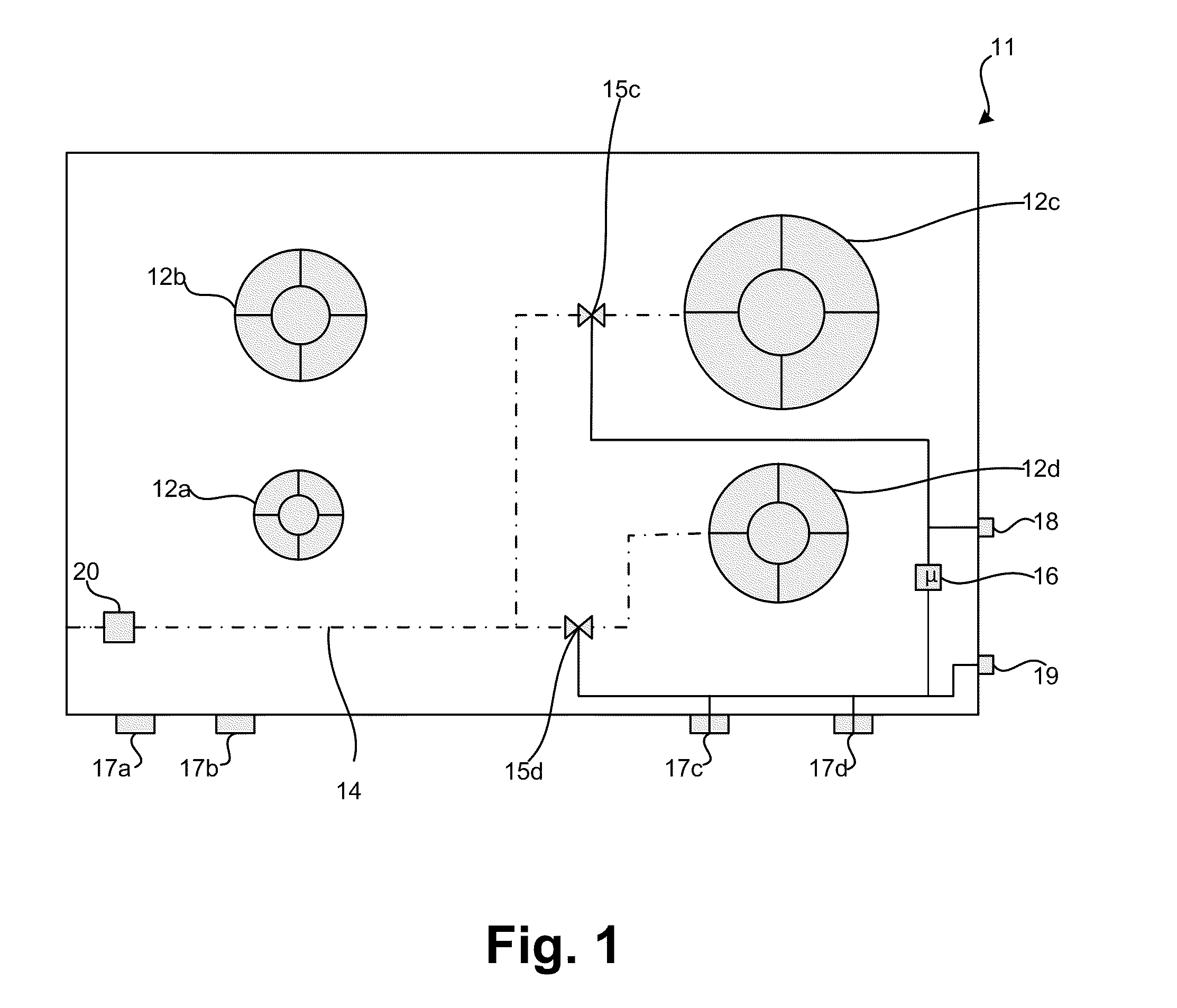
FIG. 1 shows a gas hob 11 in a schematic plan view in accordance with one embodiment of the invention. The gas hob 11 has four gas burners 12a to 12d, in a manner known per se. Here the front left gas burner 12a is a relatively small gas burner, for example for a power range of 150 W to 1200 W. The rear left gas burner 12b is a medium-sized gas burner intended and designed for a power range of 200 W to 2000 W. The rear right gas burner 12c is a relatively large gas burner designed for a power range of, for example, 500 W to 3500 W. The front right gas burner 12d is a further medium-sized gas burner that, however, is designed in accordance with an embodiment of the invention and can also operate in accordance with the invention. It can operate firstly in a low power range, which as for the gas burner 12b extends from 200 W to 2000 W, with 200 W being the lowest emitted continuous power or the lowest operating power, and with 2000 W being the highest power in the maximum setting of an...


PUM


Abstract

With a method for controlling a gas burner, the latter is supplied with gas by an electronically controllable gas valve, wherein it is supplied with gas by the gas valve in a low power range and in a high power range. Only one of the power ranges is available at any point in time, wherein in each of the power ranges a power from a minimum power to a maximum power can be preset at the gas burner using an operating element. The low power range and the high power range differ here by more than 50%.

Description

CROSS-REFERENCE TO RELATED APPLICATIONSThis application claims the benefit of German patent DE 10 2010 023 090.1, filed on May 31, 2010, the contents of which are incorporated by reference for all that it teaches.BACKGROUNDThe invention relates to a method for controlling a gas burner and a hob with several gas burners, using which, or on which, the method is performed.It is known from DE 10 2010 005 655.3, dated Jan. 19, 2010 how to set a flame circle of said gas burner depending on a diameter of a cooking pot placed on a gas burner, which flame then corresponds to a certain determined power level. This allows a gas burner to operate in an energy-optimized range.An object underlying the invention is to provide a method as stated at the outset and also a corresponding gas hob for performing said method, where problems arising from the prior art can be eliminated, and in particular, versatile and advantageous operation of a gas burner is possible.SUMMARYThis problem is solved by a me...

Claims


Application Information

Patent Timeline
IPC IPC(8): F24C3/12
CPCF23N1/002F23N2021/10F23N2035/16Y02B40/166F23N2041/08F24C3/126F23N2037/10F23N2221/10F23N2235/16F23N2237/10F23N2241/08Y02B40/00
Inventor GARTNER, NORBERTSCHAUMANN, UWE
Owner E G O ELEKTRO GERAETEBAU GMBH
Why Eureka
Try Eureka