Belt tensioning system

a belt and belt technology, applied in the field of belt tensioning systems, can solve the problems of reducing the overall efficiency of the system, reducing the efficiency of the power transfer from the motor, and often elongating the belt, so as to improve the efficiency of the belt-driven system

Inactive Publication Date: 2011-12-01
FENNER PLC
View PDF21 Cites 13 Cited by
  • Summary
  • Abstract
  • Description
  • Claims
  • Application Information

AI Technical Summary

Benefits of technology

[0004]The present system provides a system for improving the efficiency of a belt-driven system. The system includes a motor driving a drive pulley and a belt entrained about the drive pulley and a driven pulley. The driven pulley is connected to an output, such as a ventilation fan. A tensioning device engages the drive belt to provide continuous tension on the belt. The tensioner is mounted to a bracket connected with the motor. The mounting bracket includes a first leg for forming a connection with the motor. The first leg is formed to provide an adjustable connection between the mounting bracket and a mounting bracket of the motor. The first leg has an array of mounting slots arranged into rows along the length of the first leg and columns across the width of the first leg. In one embodiment, the slots are elongated along the direction of the rows. The mounting bracket further comprises a second leg projecting transverse the first leg. The second leg comprises a plurality of slots for connecting the tensioner to the mounting bracket. In one embodiment, the slots form an array of rows and columns and the slots are elongated in a direction transverse the direction in which the slots in the first leg are elongated.
[0005]The present system also includes a method for improving the efficiency of a belt-driven system. The method includes the steps of fitting a belt tensioner into an existing belt driven system that includes a motor connected to the system by a plurality of detachable connectors engaging the motor mount and a frame of the system. According to the method, a mounting bracket is provided, which has a first leg having a plurality of slots. At least one of the connectors is disconnected from the motor mount and the frame, and the first leg of the bracket is interposed between the motor mount and the frame or the connector. The connector is then reconnected thereby attaching the first leg of the bracket to the motor mount. The mounting bracket further comprises a second leg projecting transverse the first leg and having a plurality of mounting slots. The method includes the step of connecting a tensioner with the second leg of the mounting bracket so that an arm of the tensioner projects into engagement with the drive belt, and rotating the arm to bias the tensioner to provide tension to the drive belt.

Problems solved by technology

During use, the belt frequently elongates and may start to slip.
As the belt slips, the efficiency of the power transferred from the motor reduces, reducing the overall efficiency of the system.
Although such systems may improve the power transfer in some instances, such a system is susceptible to complications from deflection of the various elements during use.

Method used


Image

  • Belt tensioning system
  • Belt tensioning system
  • Belt tensioning system

Examples


Embodiment Construction

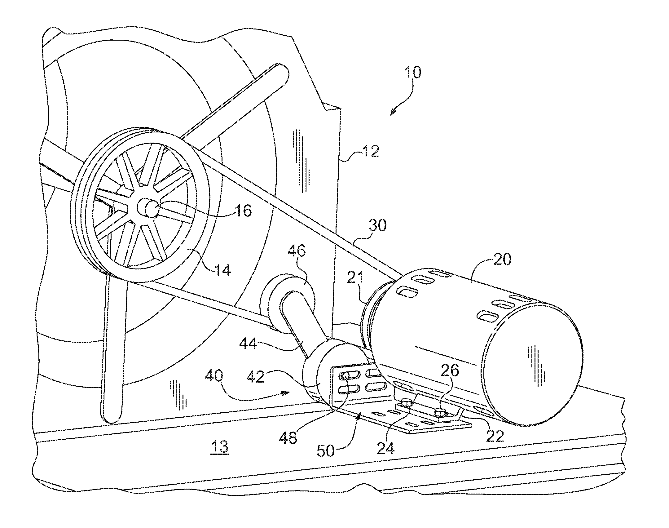
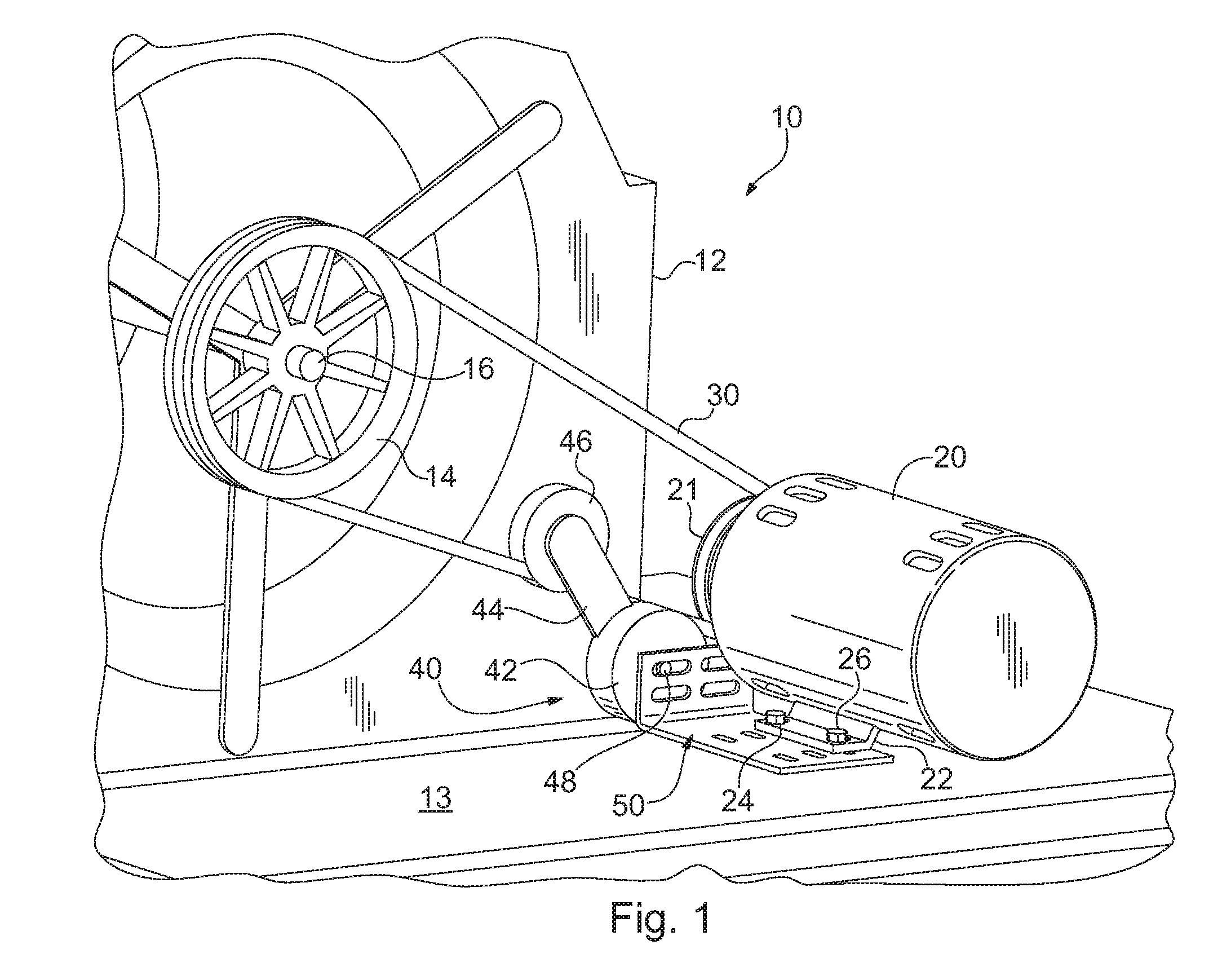
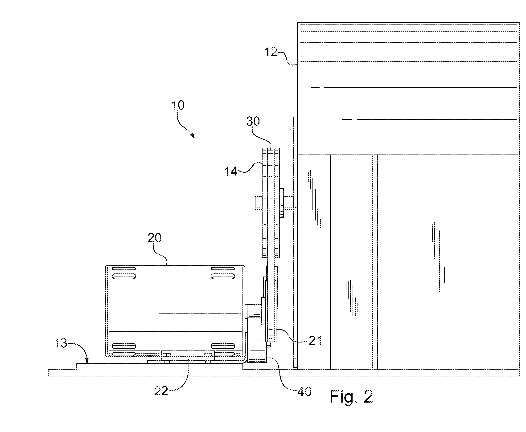
[0013]Referring now to the figures in general and to FIG. 1 specifically, a belt driven system is generally designated 10. A motor 20 drives a belt 30, which rotates a pulley 14. The pulley 14 is connected with an output shaft 16, so that when the pulley 14 rotates, the output shaft also rotates. A tensioner 40 engages the belt to tension the belt, thereby limiting slippage between the belt and either of the pulleys 14 and 21.

[0014]The system 10 may be any of a variety of belt-driven machines. However, in the present instance, the system is an HVAC system and the output shaft drives a fan, such as a ventilation fan, or a chiller. The pulley 16 is rigidly connected with the output shaft, such as by a key or by a keyless connection, such as a mounting device sold under the trademark Tran Torque by Fenner, Inc. in Manheim, Pa. An exemplary keyless connector for mounting the pulley to the shaft is disclosed in U.S. Pat. No. 5,695,297.

[0015]The system includes a frame 12, which may inclu...


PUM

PropertyMeasurementUnit
tensionaaaaaaaaaa
lengthaaaaaaaaaa
widthaaaaaaaaaa

Abstract

A system for improving the efficiency of a belt-driven system is provided. The system is particularly adapted for retrofitting tensioners onto existing belt-driven machines or to incorporate a tensioner into an the existing design of a belt-driven machine with limited changes to the specifications of the existing design. The system includes a motor driving a belt that drives a pulley. The pulley drives a shaft or other element of the system. A tensioner is provided for tensioning the belt to impede slippage between the belt and the pulley. The tensioner is connected to the motor and a frame of the system via a mounting bracket that includes a first leg and a second leg having a plurality of mounting holes adapted to cooperate with mounts on the motor and a connector of the tensioner. In one embodiment, the mounting holes of the second leg are laterally offset from one or more mounting holes of the first leg. Additionally, in one embodiment, the mounting bracket is configured so that the mounting holes in the first leg are positioned to form an array of rows and columns, and the mounting holes in the second leg are positioned to form a separate array of rows and columns.

Description

RELATED APPLICATION[0001]This application claims priority under 35 U.S.C. §119 to U.S. Provisional Patent Application No. 61 / 350,404 filed Jun. 1, 2010. The entire disclosure of the foregoing application is hereby incorporated by reference.FIELD OF THE INVENTION[0002]The present invention relates to the field of tensioners. More particularly, the present invention relates to the field of systems for tensioning a belt.BACKGROUND[0003]A variety of mechanical systems are driven by an endless belt, such as a v-belt that is driven by a motor. During use, the belt frequently elongates and may start to slip. As the belt slips, the efficiency of the power transferred from the motor reduces, reducing the overall efficiency of the system. Various improvements have been attempted to reduce the power inefficiency from belt slippage. For instance, in one system, the belt and pulleys are replaced with toothed belts driven by toothed pulley. Although such systems may improve the power transfer in ...

Claims


Application Information

Patent Timeline
Patent Type & Authority Applications(United States)
IPC IPC(8): F16H7/12B23P11/00
CPCF16H7/1281Y10T29/49826F16H2007/0842
Inventor BIGLER, JEREMY M.
Owner FENNER PLC
Why Eureka
Try Eureka