Gas Turbine Blade and Manufacturing Method Thereof

a technology of gas turbine blades and manufacturing methods, which is applied in the direction of engines, machines/engines, mechanical apparatus, etc., can solve the problems of oxidation resistance deterioration, not only the difference between the gas component and the alloy component, but also the strength of the weld material to obtain the strength equal to that of the blade material, etc., and achieves a high melting point, high proportion, and high melting point

Active Publication Date: 2011-12-08
MITSUBISHI POWER LTD
View PDF0 Cites 4 Cited by
  • Summary
  • Abstract
  • Description
  • Claims
  • Application Information

AI Technical Summary

Benefits of technology

[0014]The blade material is slowly solidified in the mold because it is a precision casting but, compared with this, the cooling rate of the weld material during solidification becomes considerably higher. Specifically, C is condensed in the liquid phase during solidification and segregates to the grain boundaries, which are the final parts to solidify, resulting in a high proportion of carbide being formed at the grain boundaries. Carbide precipitated at the grain boundaries pins the grain boundaries and works to prevent the grain boundaries from moving, so that grain boundary migration does not occur by performing the HIP treatment in the blade material where the solidification rate is low and grain boundary segregation is great and the dendritic structure during solidification is maintained. Not only carbide but also eutectic γ′ phase and a metal having a high melting point which is segregated to the grain boundaries works for preventing grain boundary migration.
[0015]On the other hand, since the weld material has a larger solidification rate, segregation is small and, since the amount of carbide formed at the grain boundaries is small, the grain boundaries are easily moved by the HIP treatment and the dendritic structure is aligned. Accordingly, the grain boundary strength is decreased, resulting in high temperature durability, fatigue strength, and the crack resistance being decreased.
[0016]It is an objective of the present invention to provide a welded part having better fatigue properties and crack resistance than that of the prior art by suppressing grain boundary alignment of the weld metal in a turbine blade where the weld repaired part or the high temperature high stress part is composed of a weld metal.

Problems solved by technology

It is difficult for the weld material to obtain a strength equal to that of the blade material because of the mixing of gaseous components during the welding process and the difference of alloy components according to importance placed on weldability and workability.
Specifically, when the amount of mixed oxygen is great, the oxidation resistance deteriorates considerably.
Moreover, there is not only the difference between the gas component and the alloy component but also differences of the solidification structure caused by differences in the solidification rate.
Accordingly, the grain boundary strength is decreased, resulting in high temperature durability, fatigue strength, and the crack resistance being decreased.

Method used


Image

  • Gas Turbine Blade and Manufacturing Method Thereof
  • Gas Turbine Blade and Manufacturing Method Thereof
  • Gas Turbine Blade and Manufacturing Method Thereof

Examples


embodiment 1

[0048]An alloy having the chemical composition as shown in table 1 was manufactured by using a vacuum melting technique and processed to a wire of about 2 mm by hot forging and cold drawing. Using this, the weld metal is formed over the blade base material by a TIG welding method and a test piece is taken to perform various evaluations.

[0049]Table 2 shows the weld material (welding wire) which is used, the weld repair process, welding atmosphere, the oxygen content, and morphology of the obtained weld metal.

TABLE 1Chemical analysis of the test sampleMajor elementComparative materialInvention material(wt. %)12345123Al3.51.20.30.61.20.60.40.5Co2221214141213Mn0.70.70.70.70.70.70.60.7Si0.20.20.20.20.20.20.20.2Cr2020202020201921Mo0001.801.51.51.8Ta00044.554.95.2W1822201518181515C0.090.090.040.040.090.090.060.07

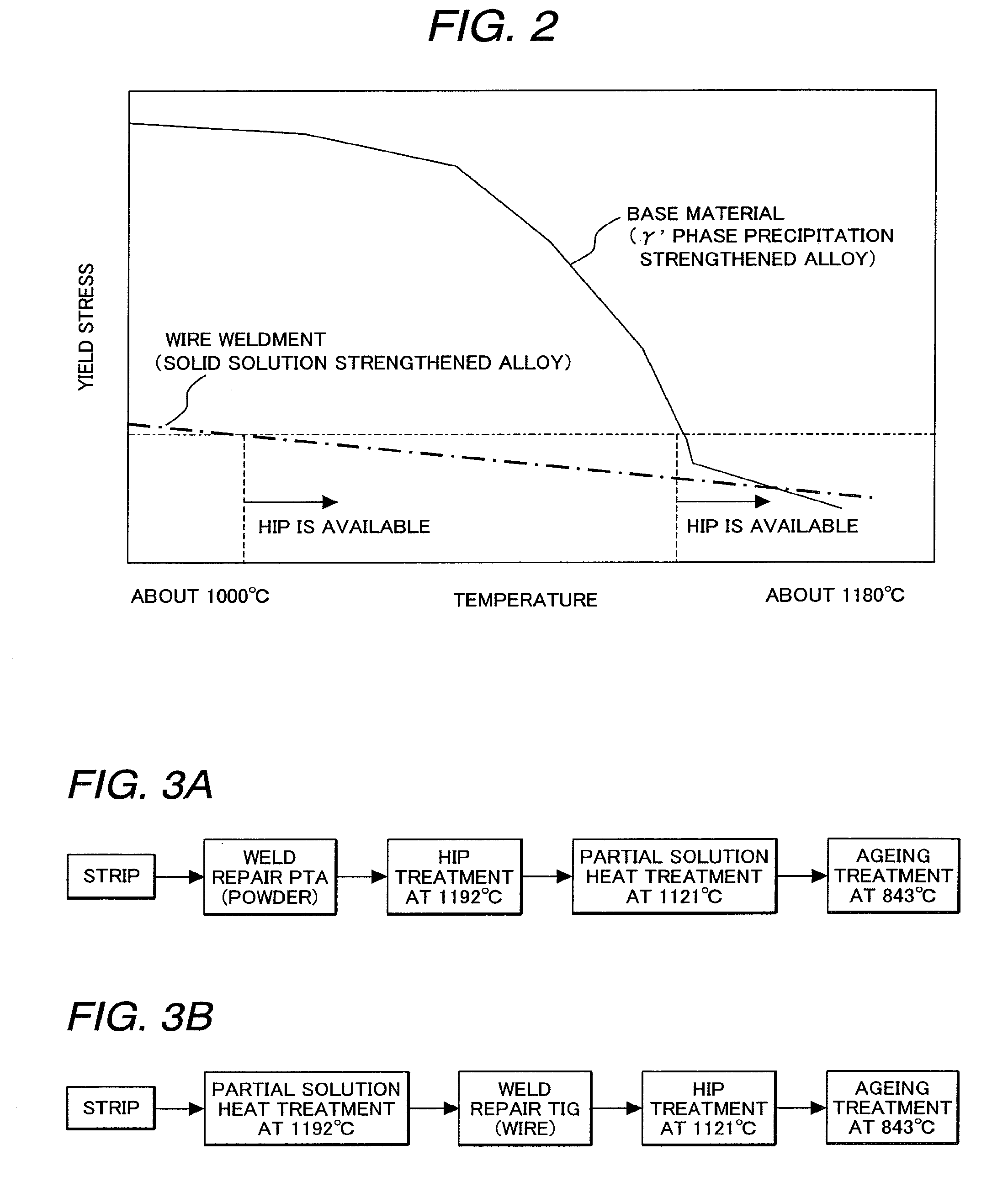
TABLE 2Weld repair process and morphologyWeldWeldrepairWeldingOxygenMor-materialprocessatmospherecontentphologyComparativeComparativeFIG. 3(a)Inert gas12 ppmFIG. 4(c)example Amater...


PUM

PropertyMeasurementUnit
temperatureaaaaaaaaaa

Abstract

In a gas turbine blade where a part of the γ′ phase precipitation strengthened type Ni-based alloy base material is composed of a weld metal, the weld metal is a Ni-based alloy containing Ta from 4.8 to 5.3 wt. %, Cr from 18 to 23 wt. %, Co from 12 to 17 wt. %, W from 14 to 18 wt. %, C from 0.03 to 0.1 wt. %, Mo from 1 to 2 wt. %, and Al of 1 wt. % or less, in which the oxygen content is 0 to 30 ppm, the Ti content from 0 to 0.1 wt. %, and the Re content from 0 to 0.5 wt. %. A blade base metal is manufactured by the step of stripping, the step of solution heat treatment where the γ′ phase is dissolved again, the step of welding in an inert gas chamber by a TIG method using a welding wire where the weld metal can be obtained, the step of HIP treatment at 1100° C. to 1150° C., and the step of an aging treatment at 835° C. to 855° C.

Description

CROSS-REFERENCE TO RELATED APPLICATION[0001]This application is a divisional application of U.S. application Ser. No. 12 / 107,796, filed Apr. 23, 2008, the contents of which are incorporated herein by reference.CLAIM OF PRIORITY[0002]The present application claims priority from Japanese application Serial No. 2007-115650, filed on Apr. 25, 2007, the content of which is hereby incorporated by reference into this application.FIELD OF THE INVENTION[0003]The present invention relates to a gas turbine blade and a manufacturing method thereof. A gas turbine blade of the present invention is preferable for a turbine blade of an industrial gas turbine. Moreover, although the matter of concern is a weld repaired blade where the weld repair is applied mainly after damage, it can be applied to one where the high temperature and high stress part is previously composed of a weld metal even if it is a new blade.RELATED ART[0004]Since the gas turbine blade is exposed to a temperature of 1000° C. or...

Claims


Application Information

Patent Timeline
Patent Type & Authority Applications(United States)
IPC IPC(8): B23P6/00B23P15/02
CPCF05D2230/235C22C19/051C22C19/05F05D2230/80Y10T29/49336Y10T29/49318F01D5/005
Inventor IMANO, SHINYAICHIKAWA, KUNIHIRODOI, HIROYUKITANAKA, KATSUMI
Owner MITSUBISHI POWER LTD
Why Eureka
Try Eureka