Life management system and method for gas turbine thermal barrier coatings

a technology of life management system and thermal barrier coating, which is applied in the field of life management system and method of gas turbine thermal barrier coating, can solve the problems of tbcs failure (or spillage), further wear on the components,

Inactive Publication Date: 2011-12-08
GENERAL ELECTRIC CO
View PDF9 Cites 32 Cited by
  • Summary
  • Abstract
  • Description
  • Claims
  • Application Information

AI Technical Summary

Benefits of technology

[0010]In yet another exemplary embodiment, a computer program product is disclosed. The computer program product includes a machine-readable medium storing instructions operable to cause one or more machines to perform operations. The operations incl

Problems solved by technology

In addition to thermal stresses, these and other components are also exposed to mechanical stresses and loads that further wear on the components.
TBCs fail (or spill) through

Method used


Image

  • Life management system and method for gas turbine thermal barrier coatings
  • Life management system and method for gas turbine thermal barrier coatings
  • Life management system and method for gas turbine thermal barrier coatings

Examples


Embodiment Construction

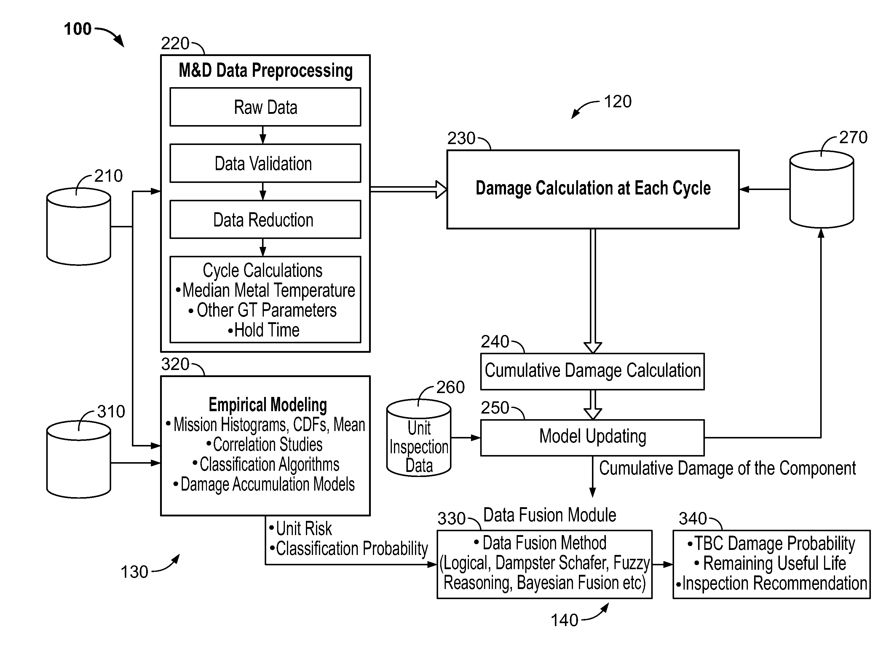
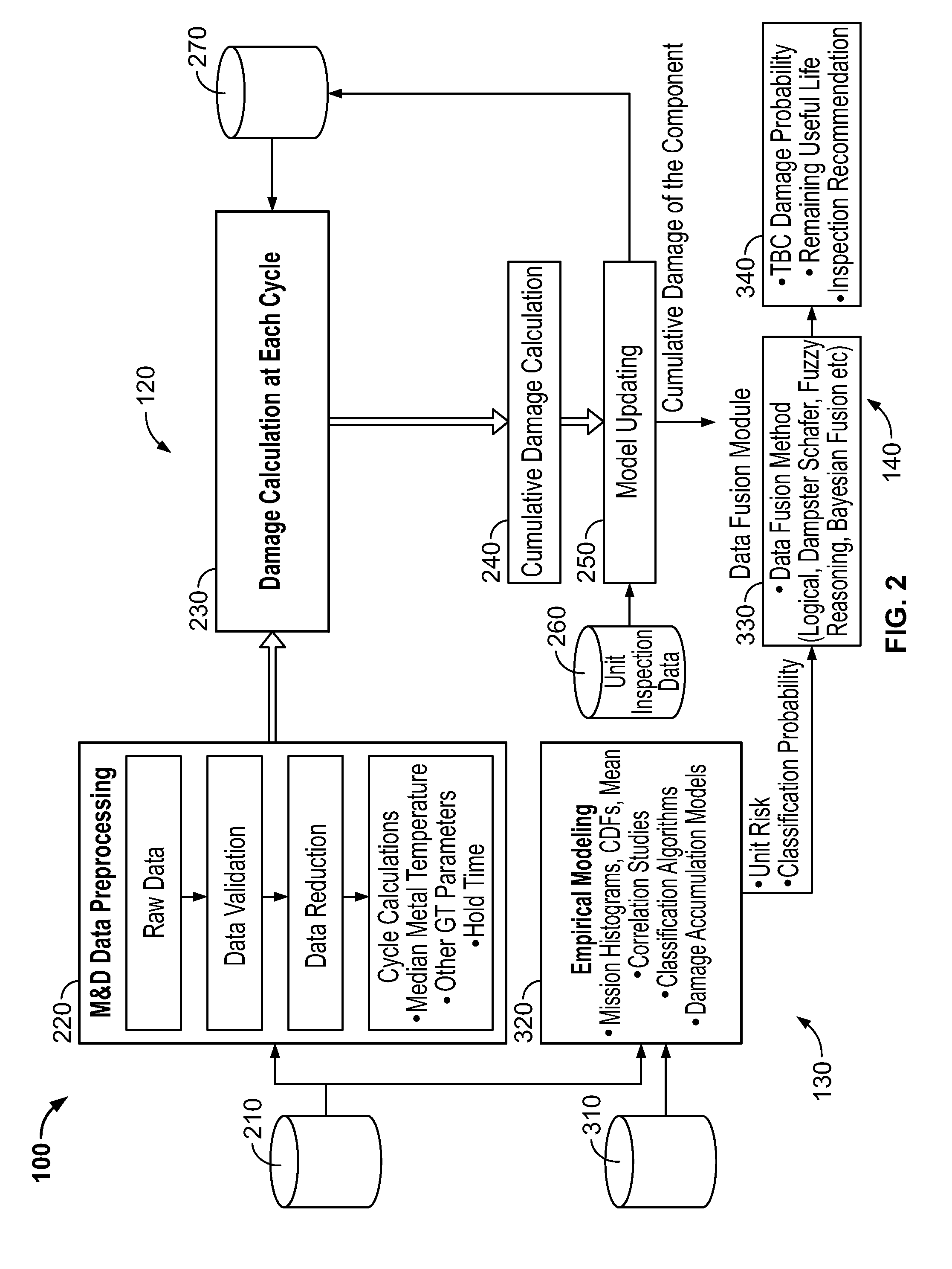
[0015]Embodiments of the present disclosure provide a method, system and computer program product for life management and monitoring of a gas turbine. The method, system and computer program product includes predicting the remaining useful life of thermal barrier coatings (TBCs) of turbine hot gas and combustion components of the gas turbine. The method, system and computer program product uses design, monitoring and diagnostics, and inspection data to determine the cumulative damage and remaining useful life of a gas turbine components having TBCs.

[0016]One advantage of the present disclosure is to provide an accurate gas turbine inspection scheduling tool that is an improvement compared to fixed schedule interval inspection.

[0017]Another advantage of the present disclosure is to provide an accurate prediction of TBC damage based on current and future risk based prediction.

[0018]One advantage of the present disclosure is to provide an improved life prediction of thermal barrier coa...


PUM


Abstract

A method, system and computer program product for life management and monitoring of a high temperature gas turbine including components having a thermal barrier coating is disclosed. The method, system and computer program product uses design, monitoring and diagnostics, and inspection data to determine the cumulative damage and remaining useful life of gas turbine components and unit risk and classification probability to determine thermal barrier coating damage probability, remaining useful life, and inspection recommendations.

Description

FIELD OF THE INVENTION[0001]The present disclosure is generally directed to gas turbines, and more particularly directed to a life management system, method and computer product to estimate thermal barrier coating performance of turbine hot gas and combustion components.BACKGROUND OF THE INVENTION[0002]Gas turbine engines include a compressor section for supplying a flow of compressed combustion air, a combustor section for burning fuel in the compressed combustion air, and a turbine section for extracting thermal energy from the combustion air and converting that energy into mechanical energy in the form of a rotating shaft.[0003]Modern high efficiency combustion turbines have firing temperatures that exceed about 1,000° C., and even higher firing temperatures are expected as the demand for more efficient engines continues. Many components that form the “hot gas path” combustor and turbine sections are directly exposed to aggressive hot combustion gasses, for example, the combustor...

Claims


Application Information

Patent Timeline
IPC IPC(8): F02C7/00G01M15/14
CPCG05B23/0283F05D2270/11F01D21/14F01D21/003
Inventor HARDWICKE, CANAN USLUNANDA, SUBRAT NMNPANDEY, ACHALESH KUMARVITTAL, SAMEERSINGH, JAGMEET
Owner GENERAL ELECTRIC CO
Why Eureka
Try Eureka