
Control stick adapted for use in a fly-by-wire flight control system, and linkage for use therein

a control stick and flight control technology, applied in the field of control sticks, can solve the problems of unnecessarily heavy and bulky couplings, interfering with other devices and freedoms, and requiring considerable spa

Active Publication Date: 2011-12-08
MOOG INC
View PDF7 Cites 3 Cited by
  • Summary
  • Abstract
  • Description
  • Claims
  • Application Information

AI Technical Summary

Benefits of technology

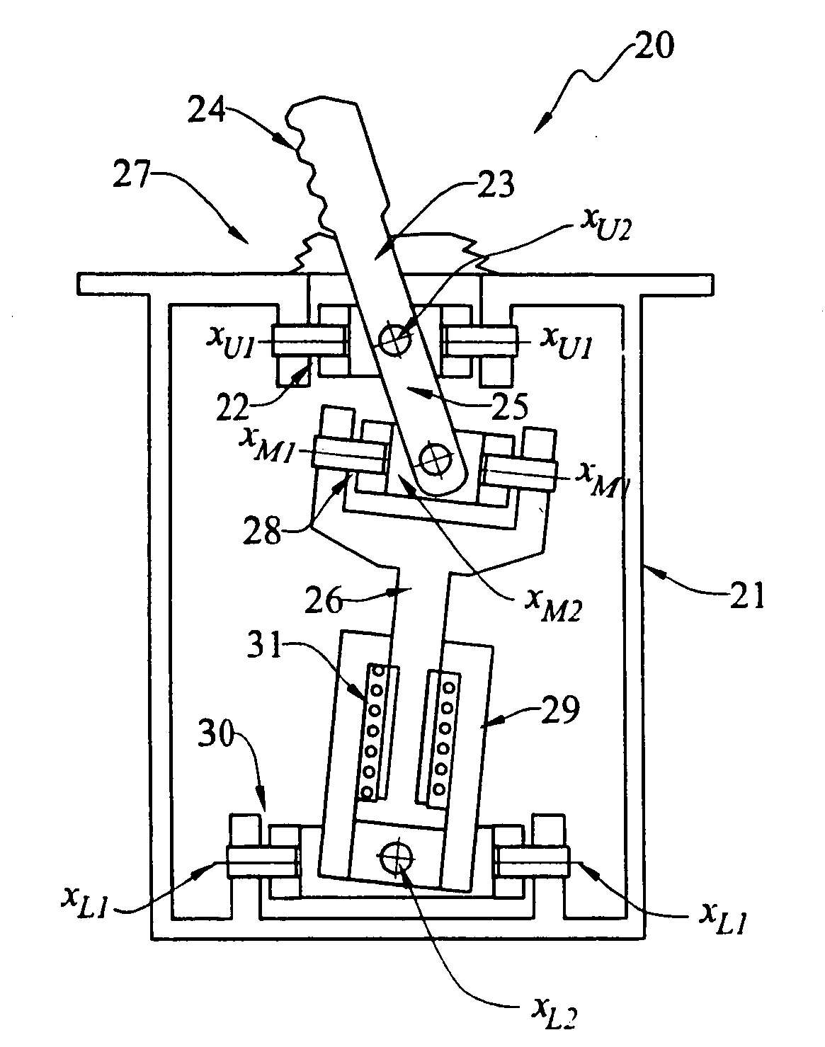
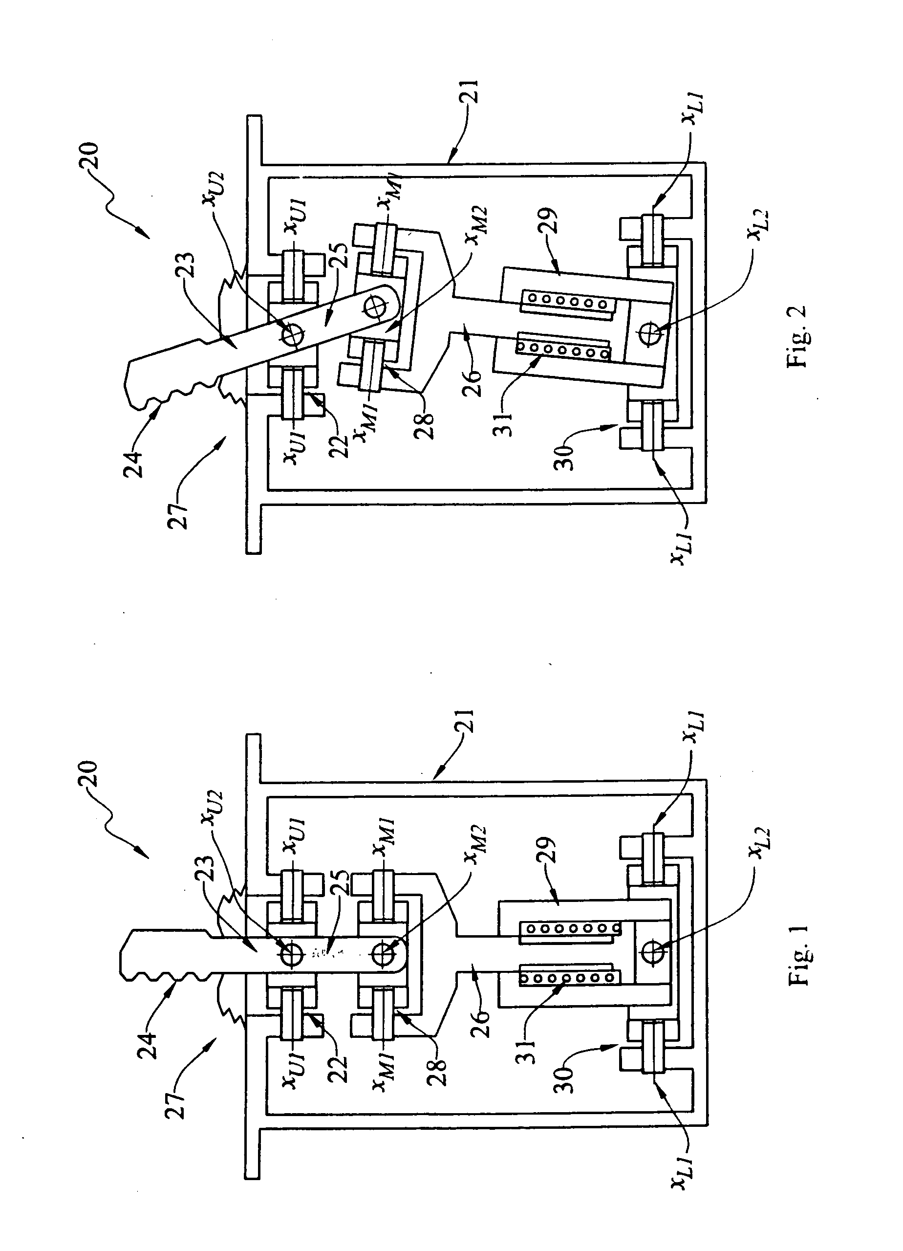
The present invention provides an improved control stick for controlling the movement of an object. The improvement includes a support, an upper member pivotally mounted on the support, an intermediate member, and a lower member. The upper member has a handle for inputting the movement of the object, and the lower member has a lower portion pivotally mounted on the support. A resilient member is used to bias the direction of movement between the intermediate and lower members. The invention also includes a linkage for mounting a handle on the support for selective compound pivotal movement about two mutually-perpendicular axes. The invention further includes an improved design for the linkage that reduces backlash and provides better control accuracy.

Problems solved by technology

However, the position and size of these joysticks often interfered with other devices and freedoms, and required considerable space to accommodate the range of permissible movement of the handle.
These couplings were unnecessarily heavy and bulky, and did not readily allow for redundancy.
However, the column wheels, joysticks and side-sticks developed heretofore have involved various mechanical linkages and couplings that have introduced friction, backlash, and the like into the movement of the control stick.
These designs are believed to have been heavy and bulky.
They are believed to have interfered with the smooth continuous transmission of manual pilot input signals from the control stick to the flight control computer, and with the smooth continuous transmission of various electrical signals to back-drive the control stick in accordance with the electrically-commanded movements and forces.

Method used


Image

  • Control stick adapted for use in a fly-by-wire flight control system, and linkage for use therein
  • Control stick adapted for use in a fly-by-wire flight control system, and linkage for use therein
  • Control stick adapted for use in a fly-by-wire flight control system, and linkage for use therein

Examples


Embodiment Construction

[0061]At the outset, it should be clearly understood that like reference numerals are intended to identify the same structural elements, portions or surfaces consistently throughout the several drawing figures, as such elements, portions or surfaces may be further described or explained by the entire written specification, of which this detailed description is an integral part. Unless otherwise indicated, the drawings are intended to be read (e.g., cross-hatching, arrangement of parts, proportion, degree, etc.) together with the specification, and are to be considered a portion of the entire written description of this invention. As used in the following description, the terms “horizontal”, “vertical”, “left”, “right”, “up” and “down”, as well as adjectival and adverbial derivatives thereof (e.g., “horizontally”, “rightwardly”, “upwardly”, etc.), simply refer to the orientation of the illustrated structure as the particular drawing figure faces the reader. Similarly, the terms “inwa...


PUM


Abstract

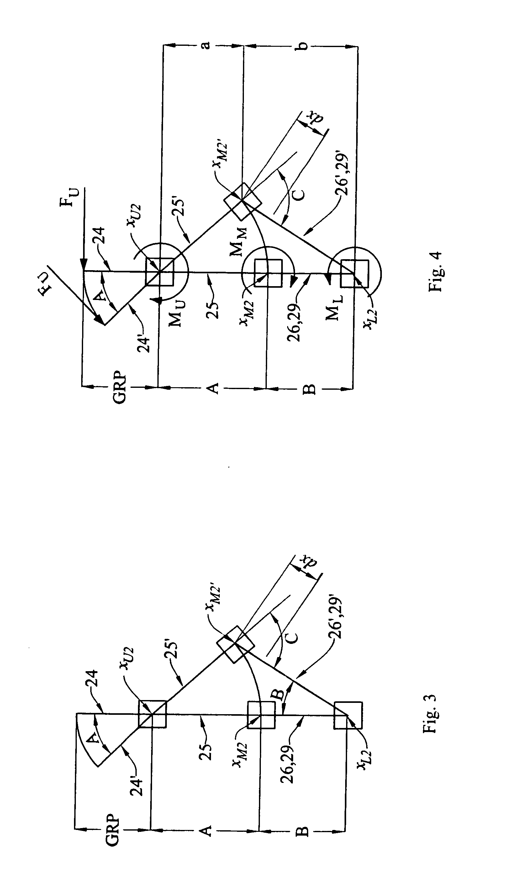
This invention provides an improvement in a control stick (e.g., joystick, side-stick, etc.) (20) adapted to control the movement of an object (e.g., an airfoil surface). The improvement includes: a support (21); an intermediately-pivoted upper member (23) mounted on the support, the upper member having an upper portion (24), and lower portion (25); an intermediate member (26) having an upper portion pivotally connected to the upper member lower portion, and having a lower portion; and a lower member (29) having a lower portion pivotally mounted on the support, and having an upper portion; and wherein the intermediate member lower portion is movably mounted on the lower member upper portion such that pivotal movement of the upper member upper portion relative to the support will produce pivotal movement of the intermediate and lower members relative to the support; and a resilient member (31) arranged to bias the direction of relative movement between the intermediate and lower members. The various pivotal connections may be provided by gimbals such that the various members are mounted for compound pivotal movement about two mutually-perpendicular axes.

Description

TECHNICAL FIELD[0001]The present invention relates generally to the field of control sticks (e.g., joysticks, side-sticks, etc.) that are adapted for use in sensing and transmitting manual operator commands to an object-to-be-moved (e.g., airfoil surfaces, etc.) in response to such commands, to improved linkages for use in mounting such control sticks on suitable supports, and to improved compound springs that are particularly adapted for use therein. One particular application contemplates the transmittal of pilot or co-pilot commands to various airfoil surfaces by a fly-by-wire flight control system.BACKGROUND ART[0002]Joysticks are well-known devices to transfer a pilot's manual input commands to various aircraft flight control surfaces. In their early forms, joysticks were usually mounted on the cockpit floor between the pilot's legs. They were typically mounted so as to enable compound pivotal movement of the stick about two mutually-perpendicular axes, representing the pitch a...

Claims


Application Information

Patent Timeline
Patent Type & Authority Applications(United States)
IPC IPC(8): G05G9/047
CPCB64C13/04F16F1/14Y10T74/20201G05G2009/04766G05G2009/04718B64C13/0421
Inventor KOPP, JOHN D.
Owner MOOG INC
Learn More