Automatic winding device for cell core

a cell core and winding device technology, applied in secondary cell manufacture, final product manufacturing, electrochemical generators, etc., can solve the problems of reducing the production efficiency of the winding device, affecting the mounting efficiency of the cell core, and the overlapped winding needles cannot firmly grip the separator during the winding process. , to achieve the effect of improving the mounting efficiency and the production quality of the cell cor

Inactive Publication Date: 2011-12-08
SAE MAGNETICS (HK) LTD
View PDF8 Cites 14 Cited by
  • Summary
  • Abstract
  • Description
  • Claims
  • Application Information

AI Technical Summary

Benefits of technology

[0007]Accordingly, an objective of the present invention is to provide an automatic winding device for...

Problems solved by technology

However, on one hand, because the separators, which are used to separate the positive electrode plate from the negative electrode plate to preventing a short circuit therebetween, are too thin, the winding needles which are overlapped cannot grip the separator firmly during the winding process.
In such a manner, the winding process becomes more complicated, thereby reducing the production e...

Method used


Image

  • Automatic winding device for cell core
  • Automatic winding device for cell core
  • Automatic winding device for cell core

Examples


Embodiment Construction

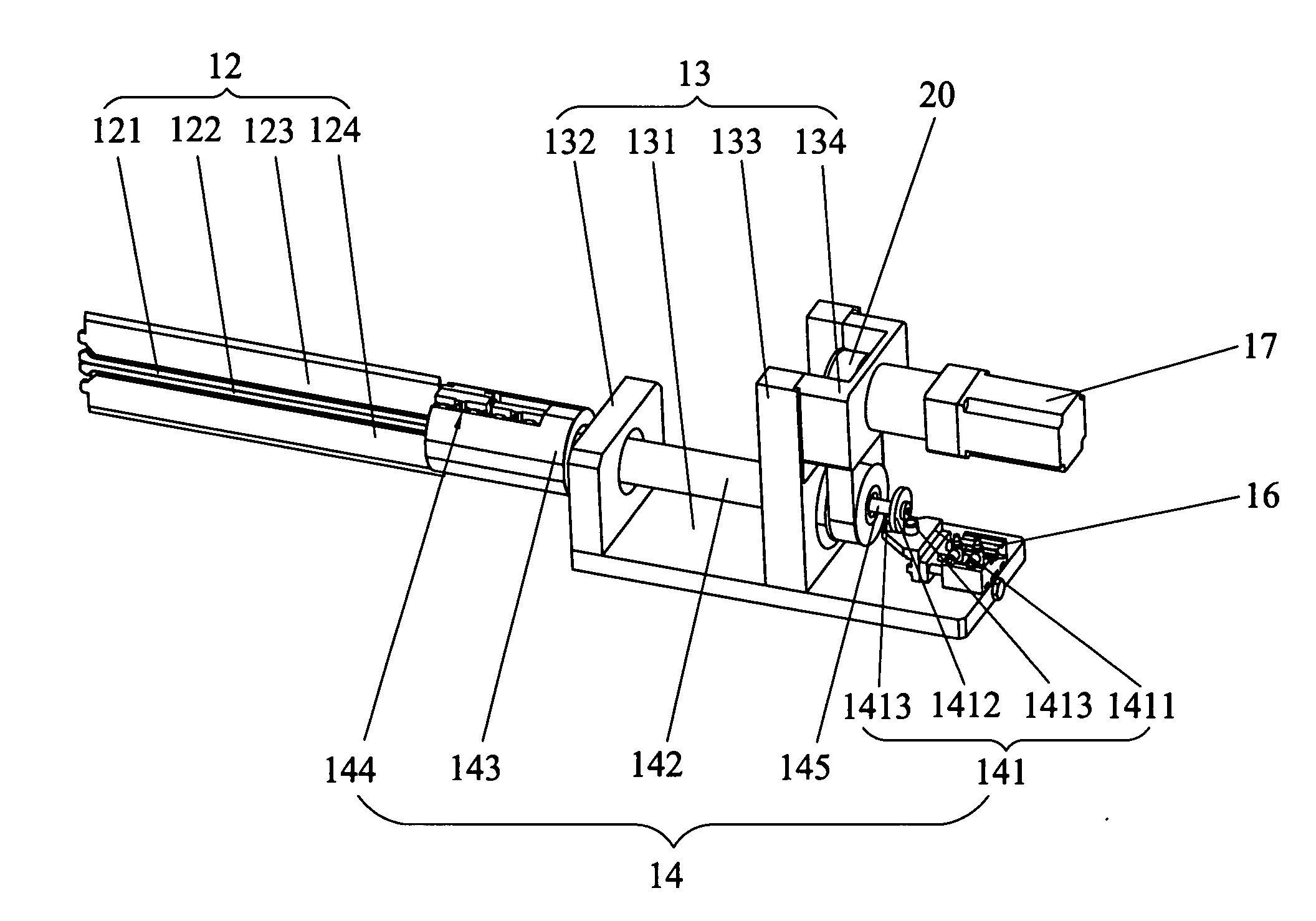
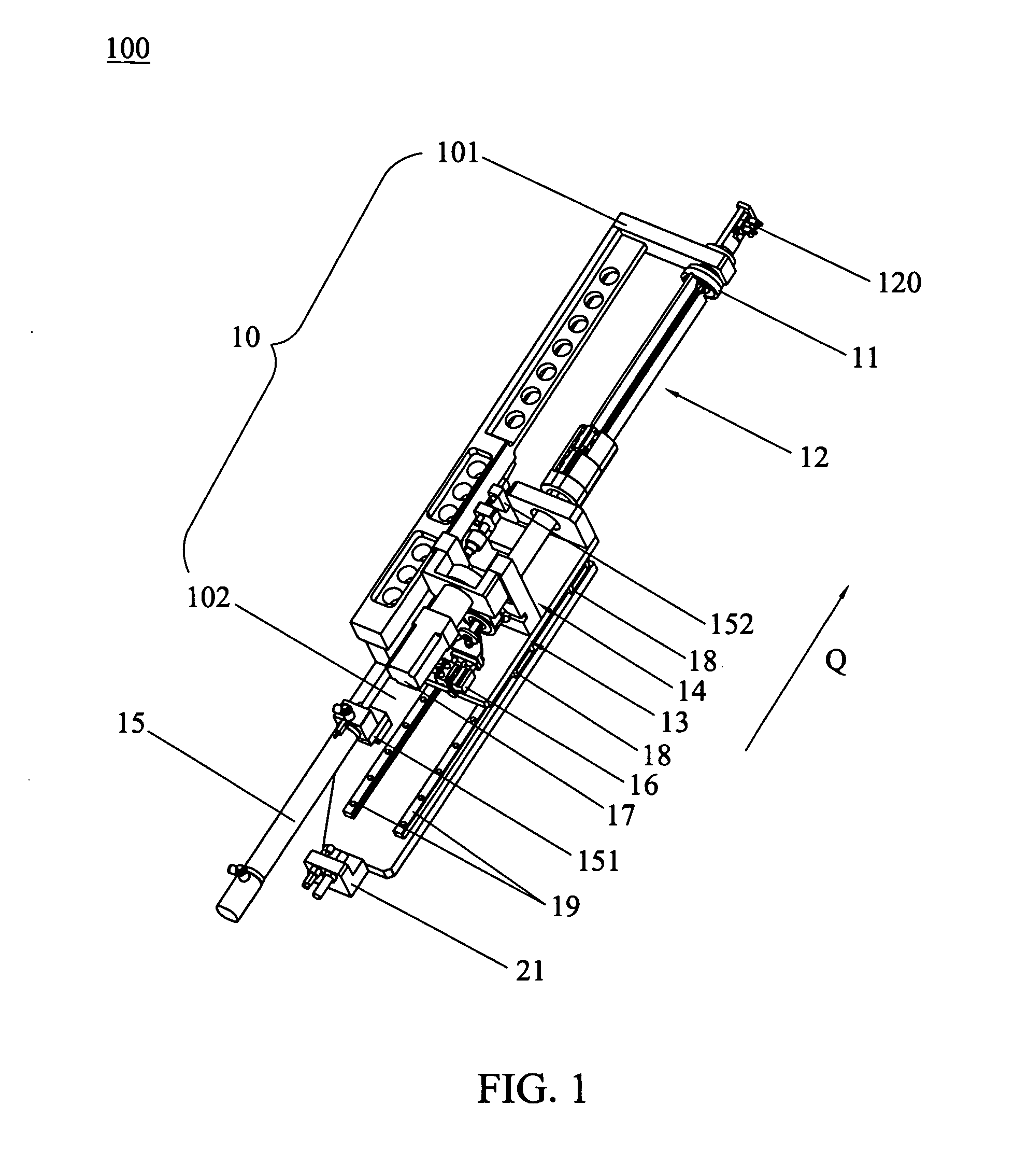
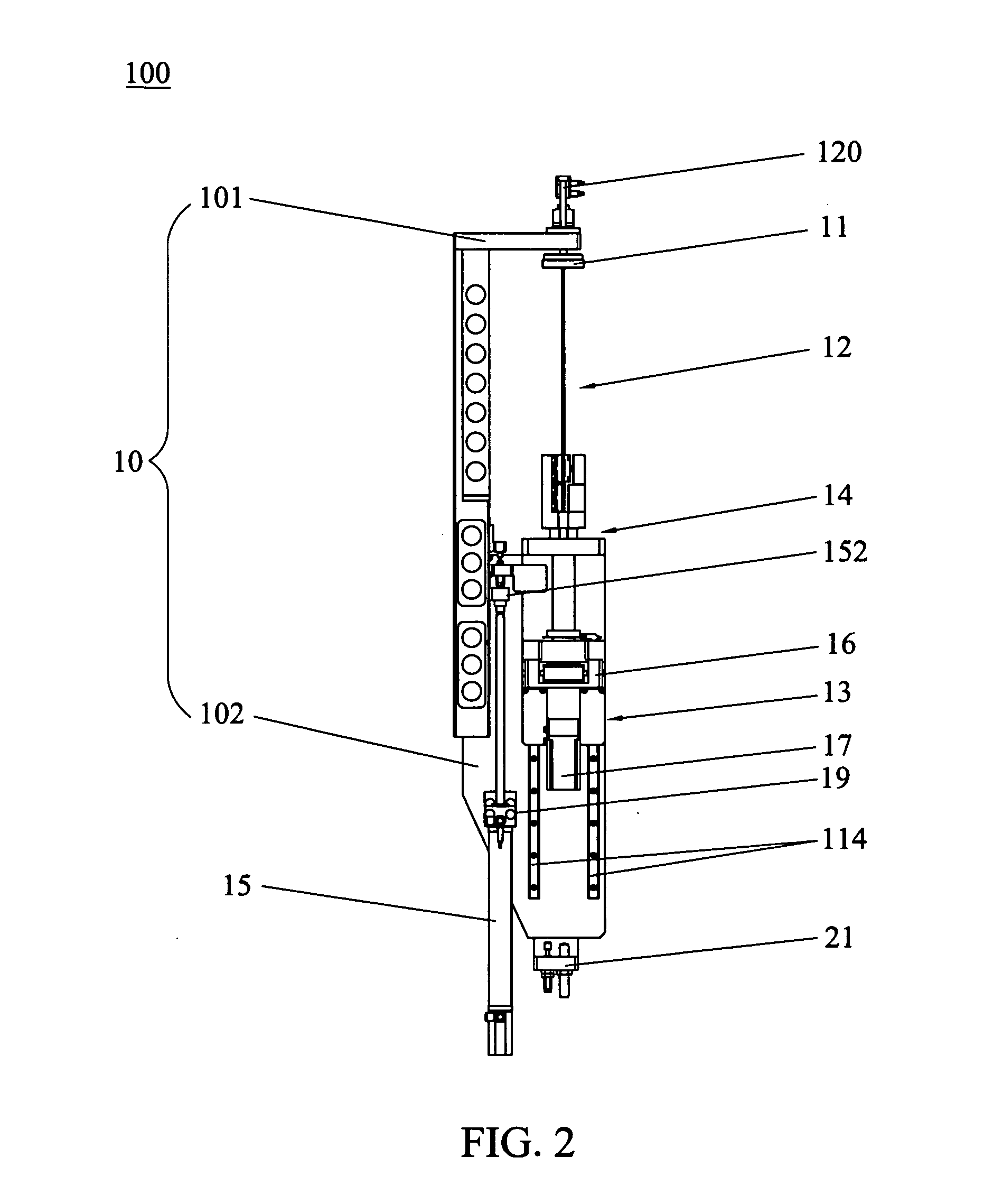
[0033]Various preferred embodiments of the invention will now be described with reference to the figures, wherein like reference numerals designate similar parts throughout the various views. FIGS. 1-2 show an automatic winding device 100 for cell core according to an embodiment of the present invention. The automatic winding device 100 includes a mounting seat 10, a locking cap 11, a winding assembly 12 and a winding assembly driving mechanism. The mounting seat 10 includes a supporting bracket 101 and a supporting seat 102 fixed to the supporting bracket 101. The locking cap 11 is fixed on the supporting bracket 101 and a cylinder 120 is fixed to the locking cap 11 for driving the locking cap 11 to move along the axis thereof. Concretely, a ball bush (not shown) is provided inside the supporting bracket 101. One end of the locking cap 11 passes through the ball bush and inserts into a bearing (not shown) which is connected to the cylinder 120. The winding assembly driving mechanis...


PUM

PropertyMeasurementUnit
Timeaaaaaaaaaa
Poweraaaaaaaaaa
Elasticityaaaaaaaaaa

Abstract

An automatic winding device for cell core includes a mounting seat, a locking cap mounted on one end of the mounting seat, a winding assembly driving mechanism mounted on the other end of the mounting seat and a winding assembly. The winding assembly comprises two winding needles and two winding plates. One end of the winding needle is fixed to the winding driving mechanism and the other end thereof opposite to the locking cap. One end of the winding plate is fixed to the winding driving mechanism and the other end thereof opposite to the locking cap. Two winding plates are disposed on both sides of the pair of winding needles respectively and contact to the pair of winding needles separably. One side of one winding needle has a concave portion and one side of the other winding needle has a convex portion that fits into the concave portion separably. A first protrusion is formed on the end of each winding needle opposite to the locking cap and a second protrusion is formed on the end of each winding plate opposite to the locking cap. A groove and a ring groove are formed in the locking cap in sequence, the first protrusion of the winding needle is locked in the groove and the second protrusion of the winding needle is locked in the ring groove.

Description

FIELD OF THE INVENTION[0001]The present invention relates to a device for manufacturing battery, particularly to an automatic winding device for cell core.BACKGROUND OF THE INVENTION[0002]At present, cylinder-shaped or square-shaped lithium battery is widely used in electronic products, such as portable computer, cell phone and music player. The production process of the lithium battery mainly includes the following steps: firstly, winding a positive electrode plate, a negative electrode plate and separators for separating the positive electrode plate from the negative electrode plate into a cylinder-shaped or square-shaped cell core; then, injecting electrolyte into the cell core; finally, introducing a metal shell to seal the cell core. And the step of winding is the most important step in the production process.[0003]The present winding machine for the lithium battery mainly includes two electrode plate supply units, two separator supply units, a separator fixing unit, a winding ...

Claims


Application Information

Patent Timeline
IPC IPC(8): H01M6/10H01M6/00
CPCH01M10/0409H01M6/005Y02P70/50
Inventor FENG, WEI
Owner SAE MAGNETICS (HK) LTD
Why Eureka
Try Eureka