
Construction Machine And A Method For Controlling And/Or Monitoring The Milling Depth Of A Construction Machine

a construction machine and milling depth technology, applied in the field of construction machines, can solve the problems of measuring devices, disadvantages of usually employed sensors, especially draw-wire sensors, and affecting the functional integrity and thus the reliability of determined lifting states

Inactive Publication Date: 2011-12-08
BOMAG
View PDF9 Cites 16 Cited by
  • Summary
  • Abstract
  • Description
  • Claims
  • Application Information

AI Technical Summary

Benefits of technology

[0010]In order to maintain the advantages in accordance with the present invention, it is preferred however when the sensor is arranged in the interior or in an interior space of the lifting column. The sensor is thus placed in this embodiment in the lifting column and is enclosed on the outside by the lifting column. The sensor is thus protected from weathering influences and can thus supply reliable measure data over considerably longer operating periods.
[0013]It is also possible to use various alternatives for implementation of the lifting column. The lifting column principally comprises an apparatus with which height adjustment of the machine frame is enabled, with which specifically the adjusting movement of the lifting column in the vertical direction is achieved. Preferably, the lifting column comprises a cylinder / piston unit for this purpose. The lifting column in this embodiment comprises a cylinder, along the cylinder axis of which a piston is guided in a longitudinal displaceable way in the cylinder in an at least partly overlapping manner. The piston can thus be displaced at least partly into the cylinder and can be pulled at least partly out of the piston. A hydraulically actuatable cylinder / piston unit is further preferred in one embodiment. This is advantageous in respect that modern road construction machines usually already comprise an existing hydraulic system, so that the present invention can be implemented rapidly in such construction machines. In order to perform the lifting movement, the piston is thus substantially displaced in the vertical direction in relation to the cylinder.
[0014]The lifting column further preferably comprises, in one embodiment, a casing which screens the lifting column towards the outside. The casing is also part of the lifting column in this embodiment. The casing substantially fulfils a screening function and protects the interior of the lifting column from damage from the outside, e.g., from introduction of dirt, etc. Such a casing can be a sleeve for example, in the interior of which the device for height adjustment such as the hydraulic cylinder / piston unit is arranged. The sleeve is preferably arranged with several elements, especially two elements, comprising an upper sleeve and a bottom sleeve. The upper and the bottom sleeve are adjusted to one another in such a way that the one sleeve, e.g., the bottom one (also designated below as the wheel carrier sleeve), is smaller than the other sleeve with respect to the diameter, e.g., the upper sleeve (also designated below as the frame-side sleeve), so that the two sleeves can be slid into one another at least in part. Furthermore, additional sealing elements or the like can be provided in order to seal the overlapping region of the two sleeves to the interior against dirt and / or humidity. The casing can further comprise respective fastening elements such as fixing links with which they are linked to the machine frame. It is now provided in accordance with the present invention that the sensor of the path measuring device is integrated in the lifting column.
[0016]In order to enable determining the extent of the lifting movement or the specific lifting position with the sensor of the path measuring device which is integrated in the lifting column, the sensor comprises, in one embodiment, a cylinder sensor element arranged in the cylinder of the hydraulic cylinder / piston unit or in the interior space of the hydraulic cylinder / piston unit and a piston sensor element which is arranged in the piston or at least in the interior space of the cylinder / piston unit in the piston. Especially when using an MG sensor, the positioning of the cylinder sensor relative to the piston sensor occurs in the manner that its distance changes with a lifting adjustment of the cylinder / piston unit. The sensor rod of the MG sensor is further arranged in the cylinder / piston unit in a further preferred embodiment in such a way that its longitudinal axis lies coaxially on the longitudinal axis or lifting axis of the cylinder / piston unit. As a result, relatively long actuating paths can be detected reliably for example in a relatively easy manner. It is advantageous with respect to the arrangement of the MG sensor in the cylinder / piston unit when the permanent magnet, the cylinder sensor element and the signal transducer are a piston sensor element, especially a modular unit on the signal transducer with the sensor rod. Alternatively, the MG sensor can also be arranged with a sensor element in the casing and with a further sensor element in a part of the piston / cylinder unit or also exclusively in elements of the casing.

Problems solved by technology

The usually employed sensors, especially draw-wire sensors, are disadvantageous as a result of their rapid wear and tear.
The distance measuring device arranged on the outside of the lifting column further has the tendency to become dirty during working operation, which has a disadvantageous effect on the functional integrity and thus on the reliability of the determined lifting states.
Moreover, the distance measuring device is subjected to weathering influences, which may also lead to malfunctions.
Finally, the application of the distance measuring device on the outside of the lifting column is often perceived as obstructive as a result of its properties where it protrudes from the outside surface of the lifting column, especially in maneuvering operation or during work in cramped conditions, e.g., when working close to the edge of a wall of a building.
It is a further special problem of the previously known arrangements for determining the lifting state of the construction machine that when transferring to construction machines with at least one horizontally pivotable wheel, the dependence of the lifting states of the construction machine on the various positions of the pivotable wheel in the horizontal plane is not taken into account and will therefore function reliably and correctly only in one specific position of the pivotable wheel.
This leads to the consequence however that the operator of the construction machine cannot use the distance measuring device at all or only to a very limited extent in pivoting states which lie outside of this specific position.

Method used


Image

  • Construction Machine And A Method For Controlling And/Or Monitoring The Milling Depth Of A Construction Machine
  • Construction Machine And A Method For Controlling And/Or Monitoring The Milling Depth Of A Construction Machine
  • Construction Machine And A Method For Controlling And/Or Monitoring The Milling Depth Of A Construction Machine

Examples


Embodiment Construction

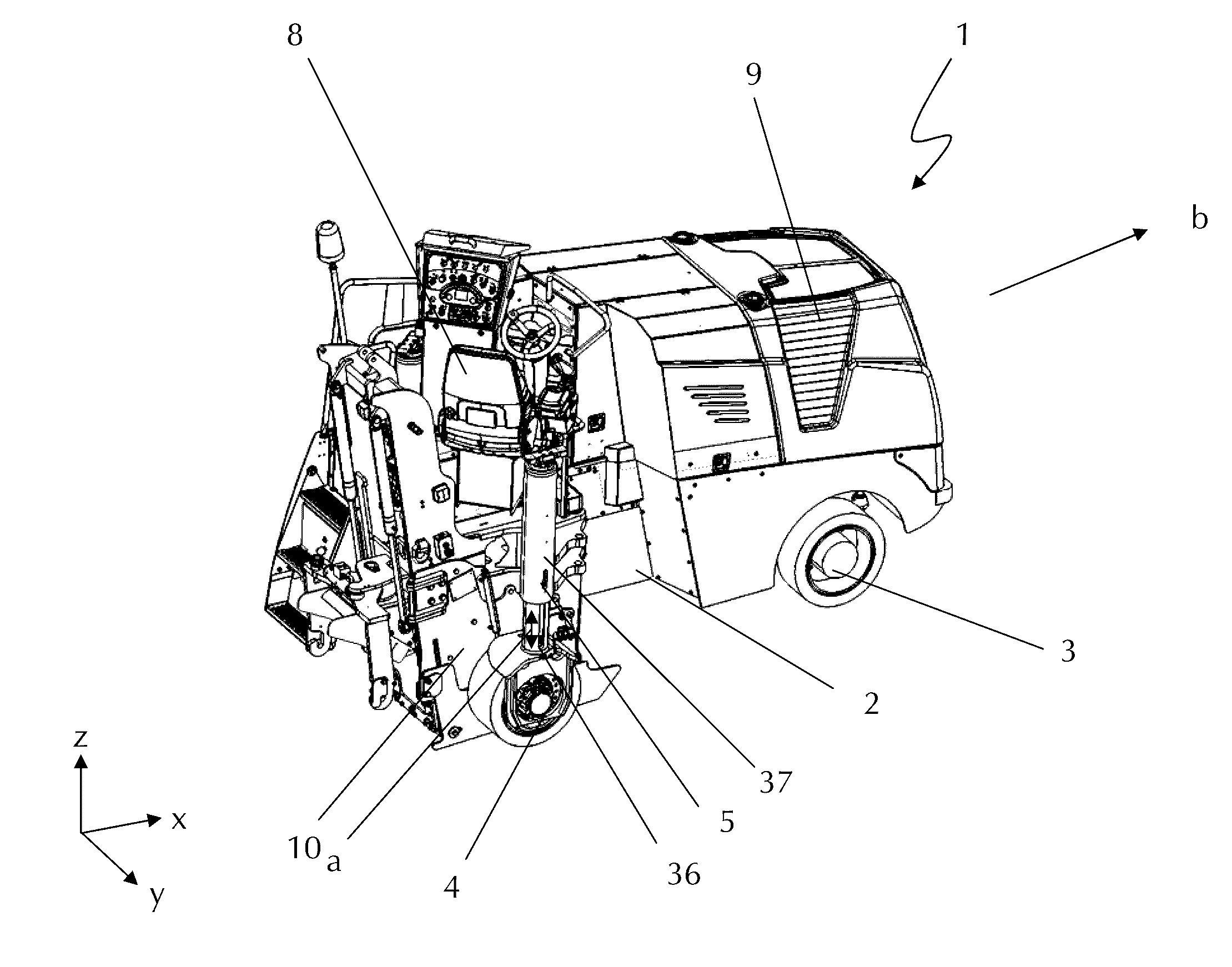
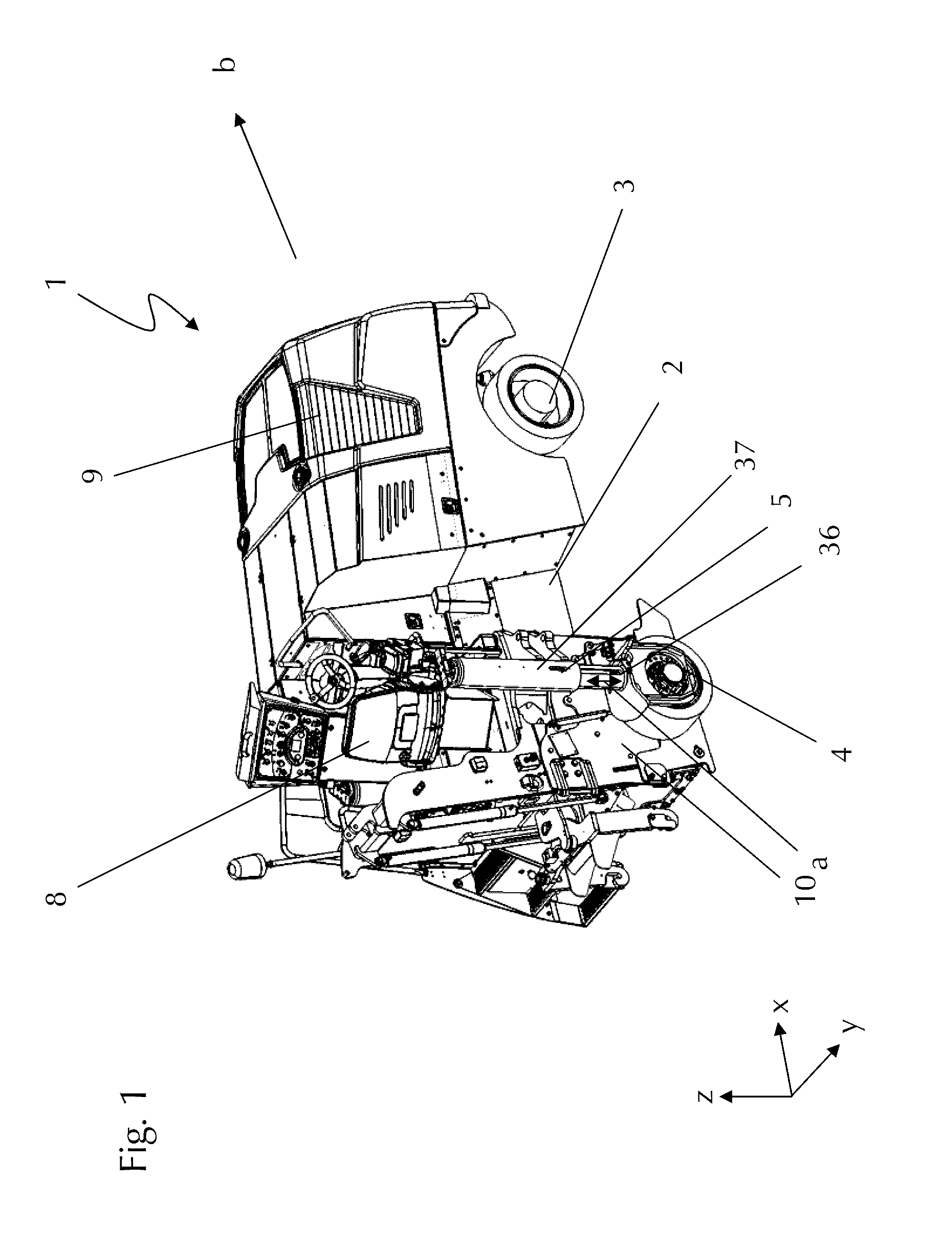
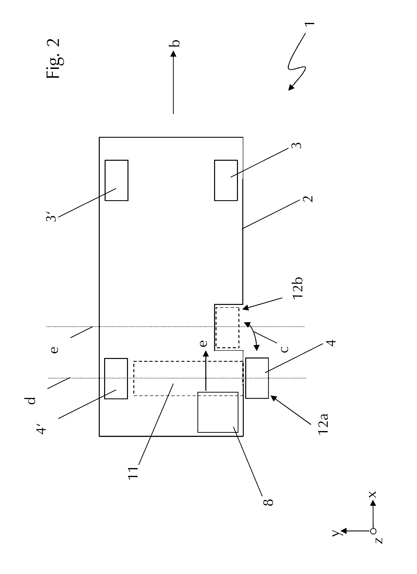
[0036]The construction machine as shown in FIG. 1 comprises a cold milling machine 1. A relevant element of the cold milling machine 1 is a machine frame 2, on which a pair of front wheels (only the front right wheel 3 is shown in FIG. 1) and a pair of rear wheels (only the right rear wheel 4 is shown in FIG. 1) are arranged. Embodiments are alternatively also possible in which only one front wheel 3 is provided. The rear wheels 4 are each linked via a lifting column 5 (only the lifting column 5 arranged on the right side is shown in FIG. 1) to the machine frame and are arranged to be height-adjustable in the vertical direction along the direction arrow a. The lifting column comprises a sleeve-like casing which is substantially formed by an upper sleeve 37 and the bottom sleeve 36. The two sleeves partly overlap and the bottom sleeve 36 can partly be slid into the upper sleeve 37. Both sleeves 36 and 37 are arranged in the manner of a hollow cylinder and jointly form a common interi...


PUM


Abstract

The invention relates to a construction machine, especially a road construction machine, comprising a machine frame and a chassis carrying the machine frame with several wheels, with at least one of the wheels being connected with the machine frame via a height-adjustable lifting column and the lifting column comprises a distance measuring device for measuring the adjustment of the lifting columns with a sensor. The invention further relates to a method for controlling and / or monitoring the working depth of a working device for processing the ground arranged on a height-adjustable construction machine, especially a road construction machine.

Description

FIELD OF THE INVENTION[0001]The present invention relates to a construction machine, such as a road construction machine for road processing, a road milling machine or cold milling machine, a recycler or a stabilizer, and a method for controlling and / or monitoring the working depth of a working device for processing the ground.BACKGROUND OF THE INVENTION[0002]In a number of construction machines, height adjustment of the construction machine, and especially a machine frame of the construction machine, is desirable with respect to the ground. Typical construction machines with such a height-adjustment function are self-propelled road construction machines, especially of the type of a road or cold milling machine, recycler or stabilizer. These construction machines are used for processing the ground and usually comprise a working drum which is arranged on the machine frame for this purpose, the rotation axis of which extends horizontally and transversely to the longitudinal direction ...

Claims


Application Information

Patent Timeline
IPC IPC(8): B60G17/00
CPCE01C23/088E01C23/01
Inventor HAUBRICH, THOMASSCHMITZ, MARCUSLAUX, ROBERTLANG, MARKUSWERNER, MARTIN
Owner BOMAG
Learn More