Touch-sensitive device and touch-sensitive display device

a display device and touch-sensitive technology, applied in the direction of electronic switching, pulse technique, instruments, etc., can solve the problems of severe periphery light leakage, production reliability is considerably reduced, and the wiring structure of the cover glass is liable to suffer scrapes, so as to achieve low light leakage and high reliability

Inactive Publication Date: 2011-12-08
WINTEK CORP
View PDF7 Cites 57 Cited by
  • Summary
  • Abstract
  • Description
  • Claims
  • Application Information

AI Technical Summary

Benefits of technology

[0006]The invention provides a touch-sensitive device and a touch-se

Problems solved by technology

According to the above design, in case the periphery of a cover glass wiring structure (such as a traces-on-lens wiring structure shown in FIG. 6) is not given any protection, the productio

Method used


Image

  • Touch-sensitive device and touch-sensitive display device
  • Touch-sensitive device and touch-sensitive display device
  • Touch-sensitive device and touch-sensitive display device

Examples


Embodiment Construction

[0025]In the following detailed description of the preferred embodiments, reference is made to the accompanying drawings which form a part hereof, and in which are shown by way of illustration specific embodiments in which the invention may be practiced. In this regard, directional terminology, such as “top,”“bottom,”“front,”“back,” etc., is used with reference to the orientation of the Figure(s) being described. The components of the invention can be positioned in a number of different orientations. As such, the directional terminology is used for purposes of illustration and is in no way limiting. On the other hand, the drawings are only schematic and the sizes of components may be exaggerated for clarity. It is to be understood that other embodiments may be utilized and structural changes may be made without departing from the scope of the invention. Also, it is to be understood that the phraseology and terminology used herein are for the purpose of description and should not be ...


PUM

PropertyMeasurementUnit
Thicknessaaaaaaaaaa
Electrical conductoraaaaaaaaaa
Transparencyaaaaaaaaaa

Abstract

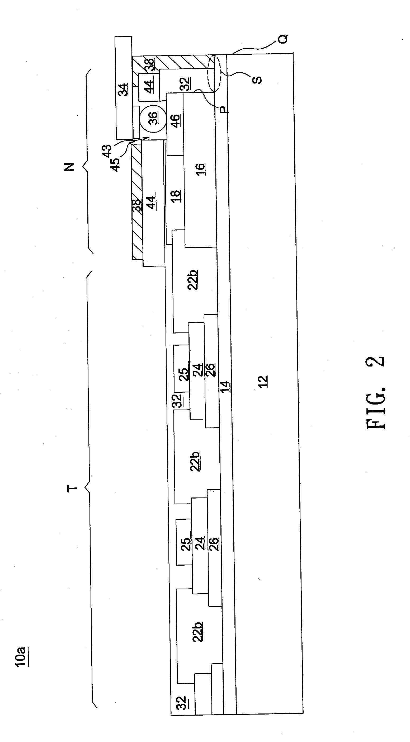
A touch-sensitive device includes a transparent substrate, a touch-sensing structure, a decorative layer, a trace layer, a passivation layer and a sheltering layer. The touch-sensing structure is disposed on the transparent substrate and located in a touch-sensitive region. The decorative layer is disposed on the transparent substrate and located in a non-touch-sensitive region, and the trace layer is disposed on the decorative layer. The passivation layer is disposed on the transparent substrate and at least covers the touch-sensing structure and the trace layer. The sheltering layer is disposed at least on the passivation layer and located in the non-touch-sensitive region.

Description

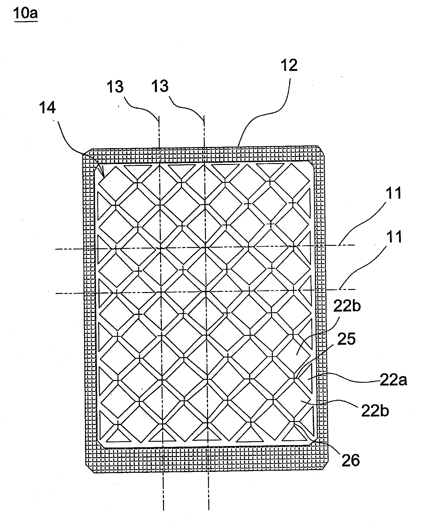
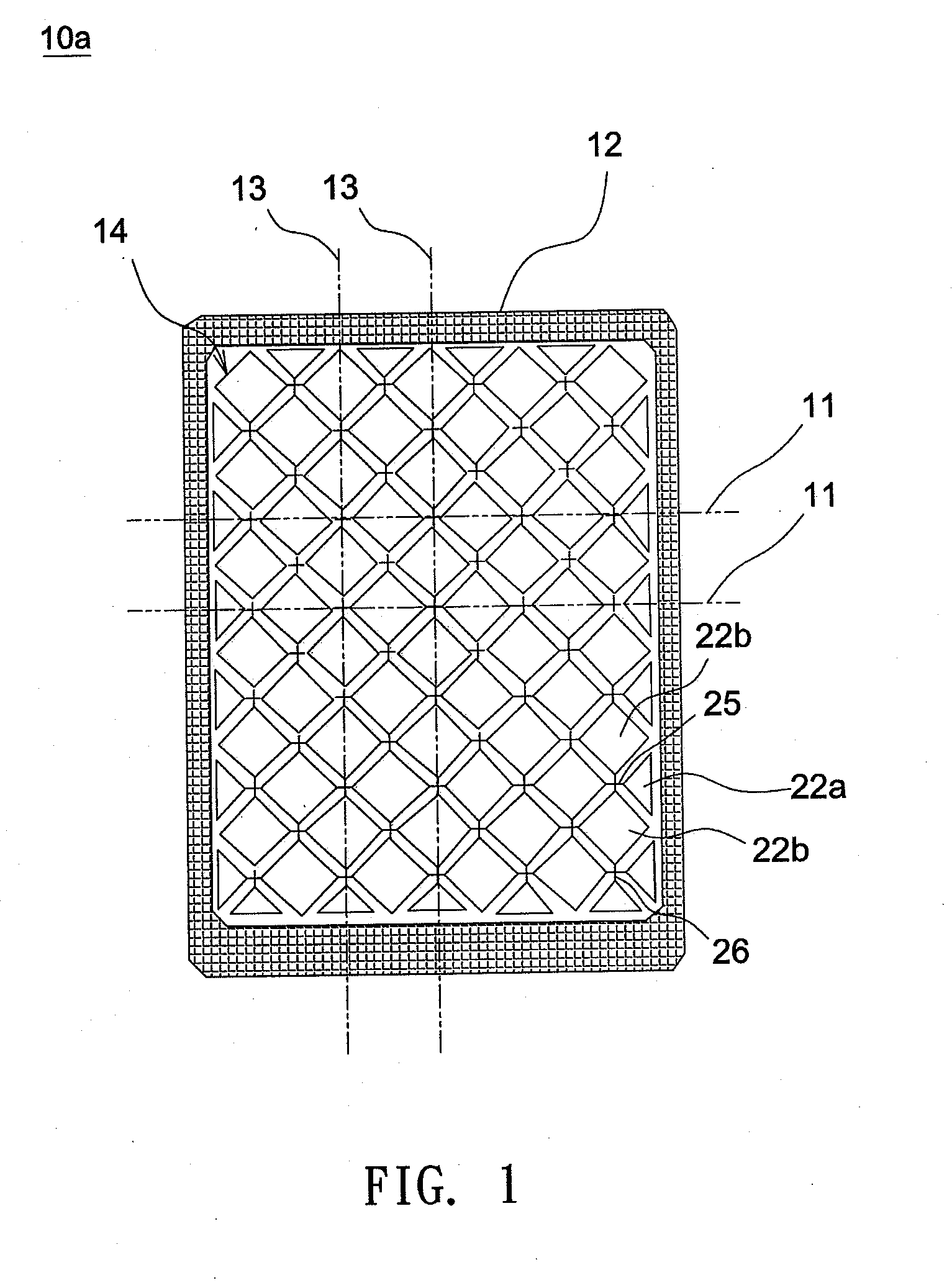
BACKGROUND OF THE INVENTION[0001]a. Field of the Invention[0002]The invention relates to touch-sensitive device and a touch-sensitive display device having high reliability and low light leakage.[0003]b. Description of the Related Art[0004]Referring to FIG. 6, a conventional touch-sensitive device 100 has a glass substrate 102, a silicide layer 104 formed on the glass substrate 102, a plurality of touch-sensing electrodes (such as X-axis electrodes 106a and Y-axis electrodes 106b), a trace layer 108, an organic dielectric layer 110 and a decorative layer 112. The X-axis electrodes 106a and the Y-axis electrodes 106b may be arranged in two directions perpendicular to each other. The X-axis electrodes 106a and the Y-axis electrodes 106b are insulated from each other by the organic dielectric layer 110, and, as shown in FIG. 6, two adjacent Y-axis electrodes 106b are connected with each other by a conductive pad 114. The trace layer 108 includes a plurality of metal traces, and the sil...

Claims


Application Information

Patent Timeline
IPC IPC(8): G06F3/041
CPCG06F3/041Y10T29/49105G06F1/1692G06F3/047H01H11/00H03K17/9618H03K2017/9602G06F3/0412H05K1/0296H05K1/0306H05K2201/0326H05K2201/09245H05K2201/10128H05K2201/10151G02B1/11G06F1/1643G06F3/044G06F3/04164G06F3/0443G06F3/0446
Inventor WU, MING-KUNGSU, KUO-CHANGCHEN, CHIA-CHILIN, YU-TING
Owner WINTEK CORP
Why Eureka
Try Eureka