Buoy systems and methods for minimizing beach erosion and other applications for attenuating water surface activity

a technology of buoys and buoys, applied in the field of buoys, can solve the problems of reducing the effectiveness of floating breakwaters, reducing the efficiency of floating breakwaters, and reducing the effectiveness of near-shore armor breakwaters, so as to achieve relative ease of deployment and less environmental consequences

Active Publication Date: 2011-12-08
MURTECH
View PDF7 Cites 29 Cited by
  • Summary
  • Abstract
  • Description
  • Claims
  • Application Information

AI Technical Summary

Benefits of technology

[0010]In accordance with one aspect of the invention there is provided a buoy for use in reducing the amplitude of waves in water. The buoy is arranged to be constrained and comprises a body configured to be resonant and impedance matched (i.e., when radiation and viscous losses are equal the buoy absorbs and dissipates the wave energy, thereby significantly reducing the energy of the transmitted waves).

Problems solved by technology

The focusing effect is due to a destructive interference between the waves radiated from the body on the incident waves.
As is known, such moving bodies act as “antennae” to produce radial waves which destructively interact with the incident waves, causing a transfer of energy (by diffraction) along the crest to the body.
The effectiveness of floating breakwaters, however, is somewhat less than near-shore armor breakwaters.

Method used


Image

  • Buoy systems and methods for minimizing beach erosion and other applications for attenuating water surface activity
  • Buoy systems and methods for minimizing beach erosion and other applications for attenuating water surface activity
  • Buoy systems and methods for minimizing beach erosion and other applications for attenuating water surface activity

Examples


Embodiment Construction

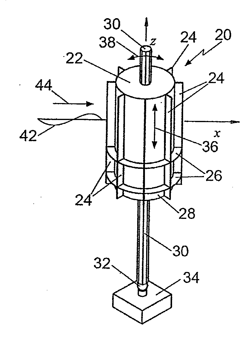
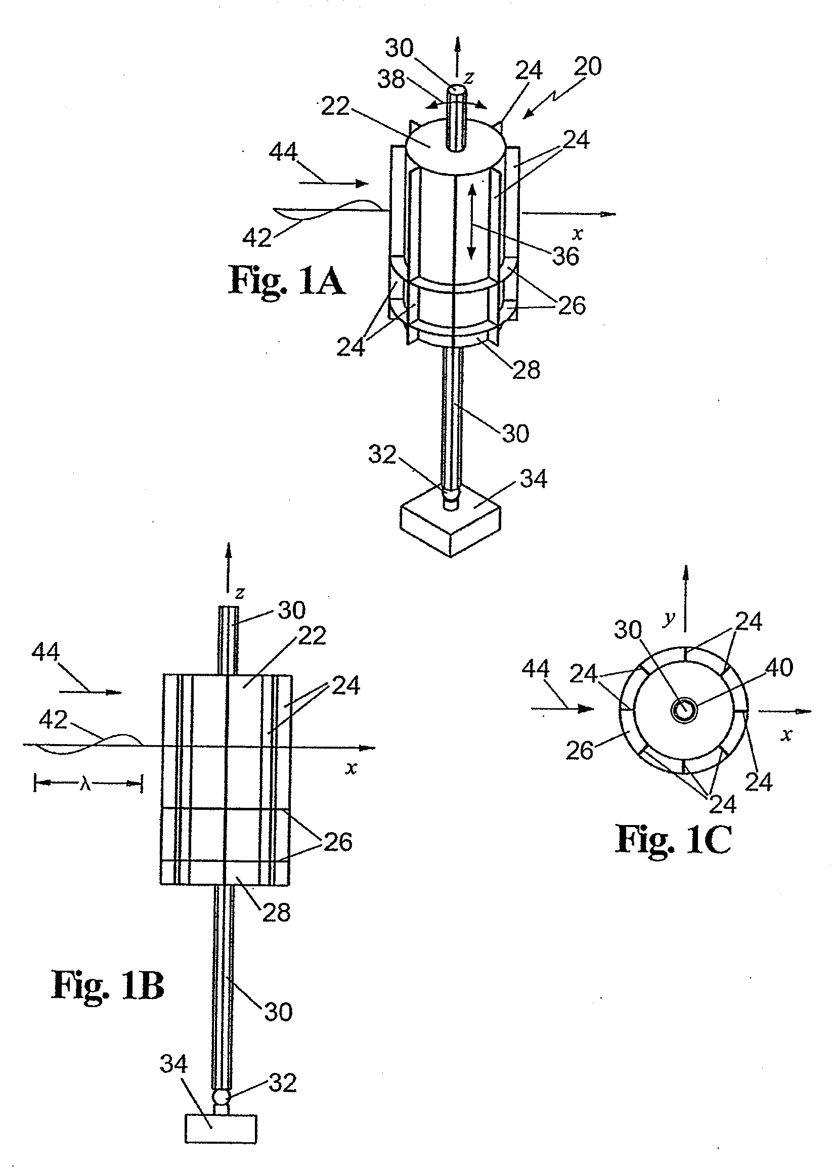
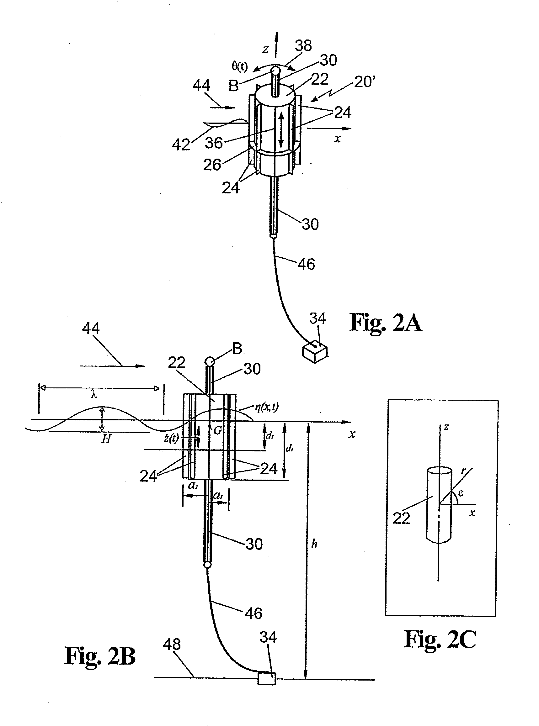
[0039]Referring now to the various figures of the drawing wherein like reference characters refer to like parts, there is shown in FIG. 1 one exemplary device constructed in accordance with this invention. The device is a resonant, impedance-matched floating “antenna buoy” designed to capture and dissipate the energy of water waves. It can be deployed singularly or in arrays of two or more to form a system that can be used to protect coastlines, harbors, waterways and moored ships. It can also be utilized to mitigate oil spills, such as the recent oil disaster in the Gulf of Mexico which has been delayed due to wind-driven heavy seas. To that end a system of a plurality of buoys constructed in accordance with this invention can act as offshore partial breakwaters to allow for the oil cleanup in the less energetic seas that are leeward of the system.

[0040]The significant defining property of the buoys of this invention is that they are impedance-matched. That is, the wave energy capt...


PUM


Abstract

A buoy for use in reducing the amplitude of waves in water and a system making use of plural buoys to create a floating breakwater. Each buoy is arranged to be constrained, e.g., connected to an anchor, and comprising a body e.g., a cylindrical member having at least one outwardly projecting fin, that is configured to be resonant and impedance matched. The buoy and anchoring approach allows for self-tuning to the chances in the wave spectrum due to the tidal or storm surge induced changes in the water depth. The body of the floating buoy is not limited to circular cylinder, and could be square, hexagonal, triangular, etc but must have at least one exterior mounted fin.

Description

CROSS-REFERENCE TO RELATED APPLICATIONS[0001]This utility application claims the benefit under 35 U.S.C. §119(e) of Provisional Application Ser. No. 61 / 350,633 filed on Jun. 2, 2010 entitled Buoy System For Floating Breakwaters, the entire disclosure of that provisional application is incorporated by reference herein.STATEMENT REGARDING FEDERALLY SPONSORED RESEARCH OR DEVELOPMENT[0002]“Not Applicable”INCORPORATION-BY-REFERENCE OF MATERIAL SUBMITTED ON A COMPACT DISK[0003]“Not Applicable”FIELD OF THE INVENTION[0004]This invention relates generally to breakwaters and more particularly to floating systems including at least one buoy arranged for reducing the amplitude of water waves for various purposes, e.g., minimizing beach erosion, creating sheltered harbors, facilitating clean-up of oil spills, calming wave energy conditions at the shoreline for sub-aquatic vegetative (SAV) or tidal vegetative growing conditions, reducing wave energy for embarkation and debarkation of offshore pla...

Claims


Application Information

Patent Timeline
Patent Type & Authority Applications(United States)
IPC IPC(8): E02B3/04
CPCE02B3/062Y02A10/11
Inventor MCCORMICK, MICHAEL E.MURTHA, ROBERT
Owner MURTECH
Why Eureka
Try Eureka