Pumping Device For Pumping Fluid

Active Publication Date: 2011-12-08
MONTANUNIV LEOBEN
View PDF2 Cites 6 Cited by
  • Summary
  • Abstract
  • Description
  • Claims
  • Application Information

AI Technical Summary

Benefits of technology

[0029]According to a further exemplary embodiment, the seal element comprises a cylindrical valve. The cylindrical valve improves the guidance of the force transmitting element or the tension rod. By using the cylindrical valve, it may be possible to guide the force transmitting element or the tension rod through the centre of a valve piston of the cylindrical valve. The valve piston may be the part of the seal element that is rigidly coupled with the force transmitting element to follow any motion of the force transmitting element. The valve piston may be moved according to the upstroke and downstroke and thus being lifted from a valve seat or pressed into the valve seat of the cylindrical valve. The valve seat may be formed in a hole provided in a central portion of a disk or plate which is installed spatially fixed in the pumping device. The force transmitting element may then extend through the hole and may reciprocate to alternatingly open or close the valve, thereby alternatingly enabling or disabling pumping. Thus, the cylindrical valve comprises firstly a mechanical guiding ability of the moving force transmitting element and secondly a sealing ability of the pumping device. Thus, fu

Problems solved by technology

Due to this compression of the sucker rods, string buckling of the sucker rods may be caused which results in higher

Method used


Image

  • Pumping Device For Pumping Fluid
  • Pumping Device For Pumping Fluid
  • Pumping Device For Pumping Fluid

Examples


Example

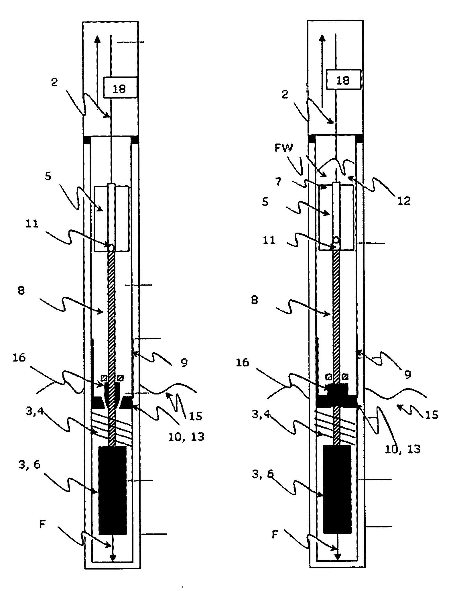
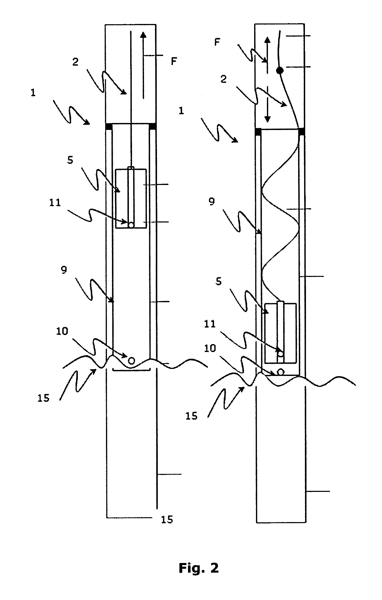
[0041]The illustrations in the drawings are schematical. In different drawings, similar or identical elements are provided with the same reference signs.

[0042]FIG. 3 illustrates a pumping device 1 according to an exemplary embodiment of the present invention.

[0043]The pumping device 1 is shown in an upstroke status (left-hand side) and a downstroke status (right-hand side).

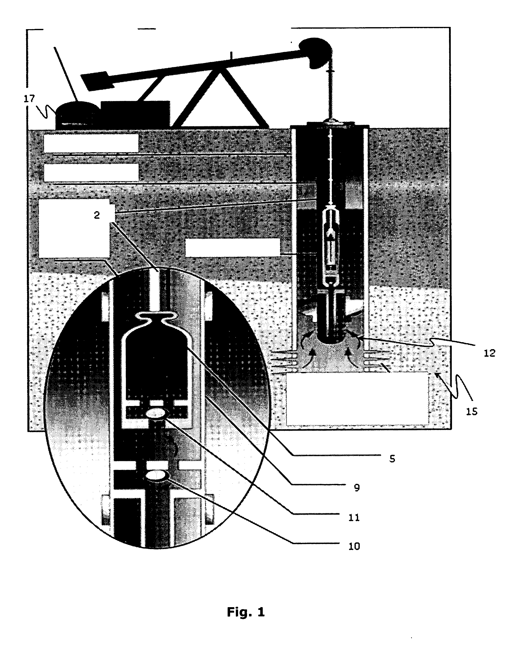
[0044]The pumping device 1 comprises a force transmitting element 2, a tension unit 3 coupled to the force transmitting element 2 and a seal element 10. The force transmitting element 2 is adapted for transferring an upstroke force and a downstroke force to a pump plunger 5 for pumping fluid 12, namely crude oil. A tension unit 3 is adapted for applying or superpositioning a tension force F to the force transmitting element 2 for keeping the force transmitting element 2 under tension during both the upstroke and the downstroke. The seal element 10 is adapted for sealing for preventing pumping fluid 12 during the d...


PUM


Abstract

The present invention describes a pumping device (1) for pumping fluids. The pumping device (1) comprises a force transmitting element (2), a tension unit (3) coupled to the force transmitting element (2) and a seal element (10). The force transmitting element (2) is adapted for transferring an upstroke and a downstroke to a pump plunger (5) for pumping fluid (12). The tension unit (3) is adapted for applying a tension force (F) to the force transmitting element (2) for keeping the force transmitting element (2) under tension during the upstroke and the downstroke. The seal element (10) is adapted for sealingly preventing pumping fluids (12) during the downstroke and for enabling pumping fluid (12) during the upstroke. A part (16) of the seal element (10) is rigidly coupled with the force transmitting element (2).

Description

FIELD OF THE INVENTION[0001]The invention relates to a pumping device, in particular to a sucker rod pump, and a method for pumping fluid as well as a use of the pumping device.BACKGROUND OF THE INVENTION[0002]Sucker rod pumps are used throughout the entire industry and are adapted for pumping various kinds of liquids. These pumps are also very popular in oil well production and cover a large percentage of oil wells on artificial lift worldwide. There are three basic types of constructions like insert pumps, tubing pumps and casing pumps.[0003]However, the pump principle is similar for the three different pump types. In such pump devices, in particular in sucker rod pumps, a pump is actuated in a defined depth by the sucker rod string which is hence reciprocated by a beam pumping unit at the surface. The pump is basically composed of a pump plunger that is movably supported in the bore hole and that comprise a travelling valve. At the bottom of the bore hole a pump barrel is install...

Claims


Application Information

Patent Timeline
IPC IPC(8): F04B49/06F01B9/00
CPCE21B43/127F04B47/026F04B47/02
Inventor HOFSTATTER, HERBERT
Owner MONTANUNIV LEOBEN
Why Eureka
Try Eureka