
Method and system for controlling hydraulic apparatus for continuously variable transmission of hybrid vehicle system

Inactive Publication Date: 2011-12-08
IND TECH RES INST
View PDF17 Cites 18 Cited by
  • Summary
  • Abstract
  • Description
  • Claims
  • Application Information

AI Technical Summary

Benefits of technology

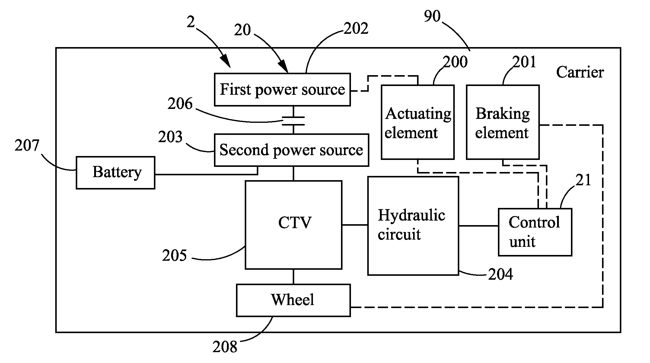
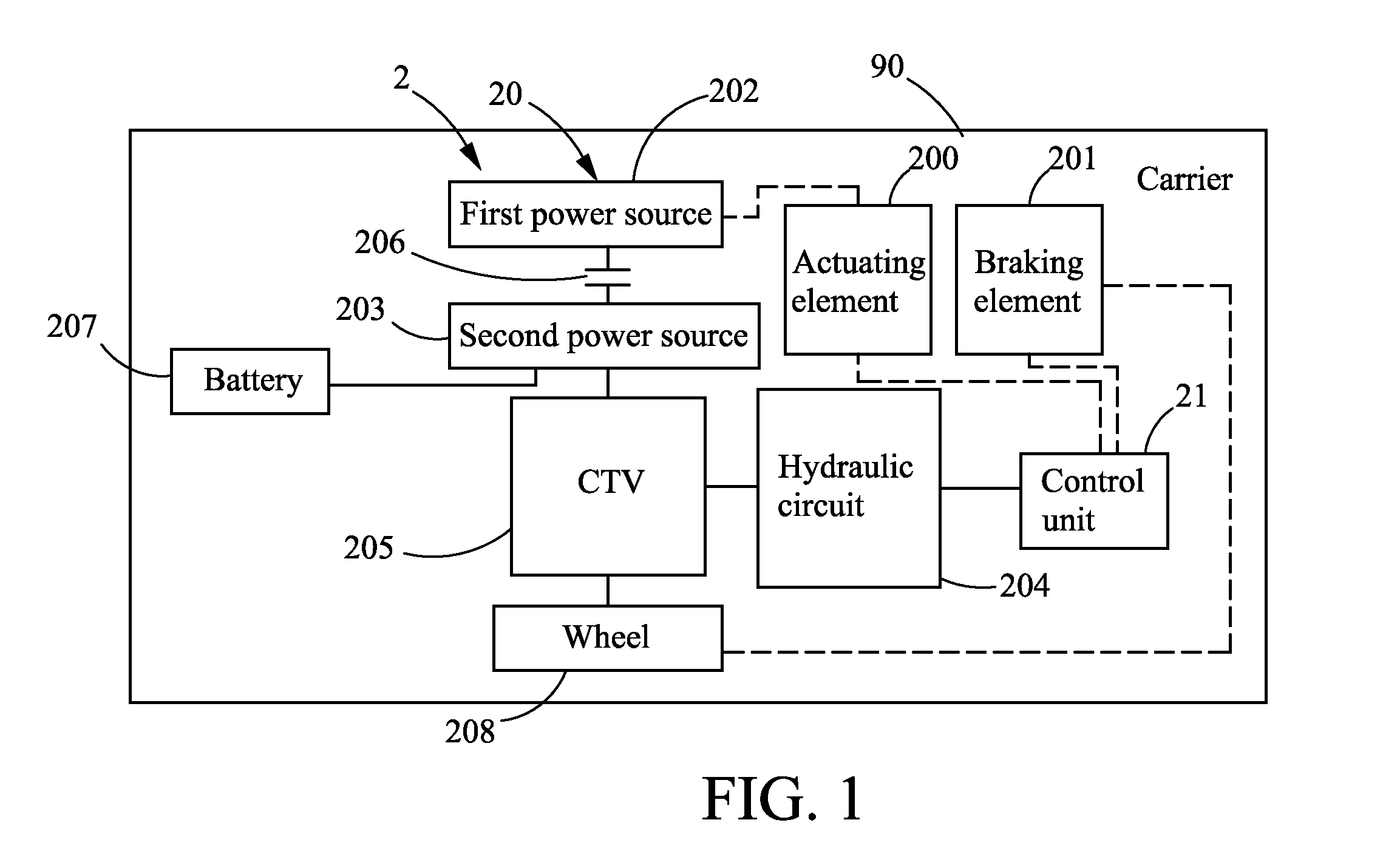
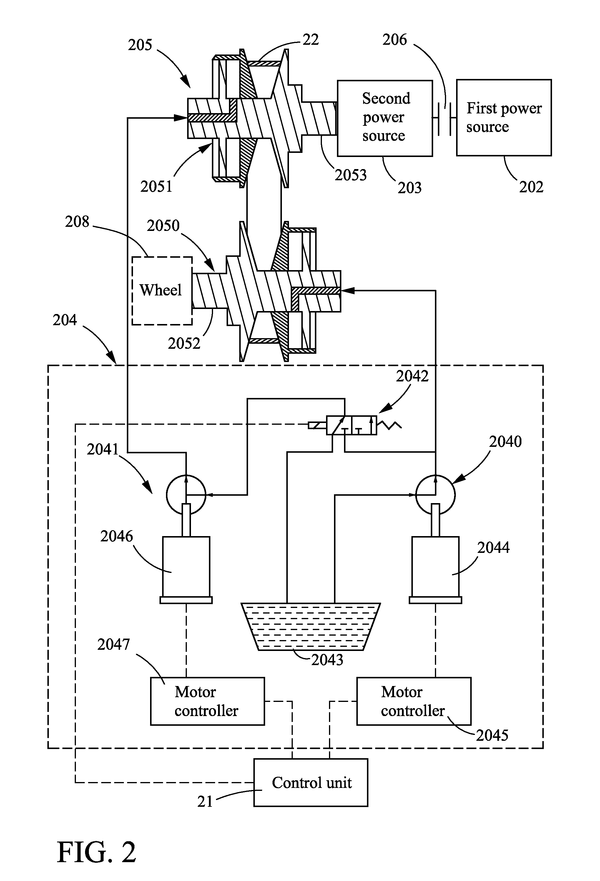
[0005]The present disclosure related to a method and system for controlling hydraulic apparatus for continuously variable transmission of hybrid vehicle system, in which a simple valve switch is used for controlling hydraulic pumps of a hydraulic apparatus to be serial connected or parallel connected, and thus the operation control of the hydraulic circuit connecting the hydraulic pumps is alleviated. Wherein, by the construction of the hydraulic circuit to be serial-connected, the pressure load of the corresponding hydraulic pumps can be reduced, in that hydraulic pressure generated from a first hydraulic pump that is simultaneously exerted upon two pulleys coupled respectively to an input shaft and an output shaft of a CVT system is used as a clamping force, while a second hydraulic pump that is serially connected with the first pump is used for boosting only the hydraulic pressure working upon the input shaft so that a pressure difference between the two pulleys is caused and used for determining a gear ratio for the CVT system. It is noted that the two hydraulic pumps are designed to function differently in this hydraulic circuit, i.e. one of the two is used for generating the clamping force, while the other is used for causing pressure difference to be used for determining a gear ratio for the CVT system, by that the hydraulic pressure control in the hydraulic circuit is comparatively more precise and accurate. On the other hand, by the construction of the hydraulic circuit to be parallel-connected, the hydraulic pressure generated from one of the two hydraulic pumps and a portion of hydraulic pressure generated from the other hydraulic pump are simultaneously used for causing the clamping force, while the pressure difference between the two hydraulic pumps is used for determining a gear ratio for the CVT system.
[0006]In addition, the present disclosure related to a method and system for controlling hydraulic apparatus for continuously variable transmission of a hybrid vehicle system, by that when a brake of the hybrid vehicle system is being stepped, the power transmission is reversed for causing the gear ratio to increase, and thereby, the connection of the hydraulic circuit that was originally in serial connection will be converted into parallel connection or in some condition that it will be changed into a reversed serial connection opposite to the original serial connection, and thus the rotation speed of the input shaft is increased so as to facilitate the power recovery operation of a power generator in the hybrid vehicle system during braking.

Problems solved by technology

However, such CVT design is not capable of responding to all kinds of driving conditions fully and effectively that the engine using such CVT is not able to operate with optimum power output.
In addition, as the aforesaid CVT is simple in structure, it is mostly used in motorscooters despite of its small torque output and unsatisfactory operation efficiency.

Method used


Image

  • Method and system for controlling hydraulic apparatus for continuously variable transmission of hybrid vehicle system
  • Method and system for controlling hydraulic apparatus for continuously variable transmission of hybrid vehicle system
  • Method and system for controlling hydraulic apparatus for continuously variable transmission of hybrid vehicle system

Examples


first embodiment

[0040]The method performed in this embodiment is basically the same as the one shown in FIG. 6, but is different in that: the method of the embodiment further comprises the step of: using a feedback control process for maintaining the gear ratio at a constant value, as the step 36 shown in FIG. 8. Please refer to FIG. 9A, which is a flow chart depicting the steps performed in a process for feedback controlling the gear ratio according to the present disclosure. The steps shown in FIG. 9B illustrates the performing of the feedback control process when the valve is switched for enabling parallel connection. In FIG. 9A, the feedback control process will start from the step 360a. At step 360a, the rotation speeds of the input shaft and the output shaft are measured while diving one using another so as to obtain an operation gear ratio; and then the flow proceeds to step 361a. As shown in FIG. 3B, the second controller 211 is configured to receive rotation signals 2115, 2116 respectively...

second embodiment

[0041]Please refer to FIG. 9B, which is a flow chart depicting the steps performed in a process for feedback controlling the gear ratio according to the present disclosure. The steps shown in FIG. 9B illustrates the performing of the feedback control process when the valve is switched for enabling parallel connection. In FIG. 9B, the feedback control process will start from the step 360b. At step 360b, the rotation speeds of the input shaft and the output shaft are measured while diving one using another so as to obtain an operation gear ratio; and then the flow proceeds to step 361b. At step 361b, an evaluation is made to determine whether the acquired operation gear ratio is larger or smaller than the gear ratio; if the gear ratio larger, then the flow proceeds to step 362b for enabling the hydraulic pressure of the first hydraulic pump to increase; otherwise, the flow proceeds to step 363b for enabling the hydraulic pressure of the second hydraulic pump to decrease; and thus enab...


PUM


Abstract

The present invention provides a method and system for controlling hydraulic apparatus for CVT of a hybrid vehicle system, which adjust rotation speed of an input axial and output axial by means of hydraulic pressure generated from a first and a second hydraulic pump and guided through hydraulic circuits coupled to the input and output shafts for controlling gear ratio and output torque of the CVT. Meanwhile the present invention determines serial or parallel connection between the first and second hydraulic pumps according to the operation mode and status of the hybrid vehicle system so as to control the output of the CVT effectively. Besides, the present invention controls the hydraulic pressure of the first and second hydraulic pump for controlling the gear ratio of CVT such that the input source such as engine or motor can be operated in the optimized zone thereby reducing the energy consumption.

Description

TECHNICAL FIELD[0001]The present disclosure relates to a continuously variable transmission (CVT) control method and system, and more particularly, to a method and system for controlling hydraulic apparatus for continuously variable transmission of hybrid vehicle systems.TECHNICAL BACKGROUND[0002]In the early continuously variable transmission (CVT) design, there are centrifugal masses disposed inside the movable halve of it's active pulley while enabling the same to be activated in response to the rotation of engine, by that the belt radius pitch of the active pulley is changed accordingly and thus the rotation speed of its transmission shaft as well as the output torque are changed consequently. However, such CVT design is not capable of responding to all kinds of driving conditions fully and effectively that the engine using such CVT is not able to operate with optimum power output. In addition, as the aforesaid CVT is simple in structure, it is mostly used in motorscooters despi...

Claims


Application Information

Patent Timeline
IPC IPC(8): F16H59/14
CPCF16H61/0025F16H61/0031F16H2059/704F16H2059/148F16H61/66272
Inventor HSIEH, KAI-CHINGGU, HUAN-LUNGWEI, TSENG-TE
Owner IND TECH RES INST
Learn More