Cooling system with increased efficiency

Active Publication Date: 2011-12-15
ROCKY RES
View PDF3 Cites 30 Cited by
  • Summary
  • Abstract
  • Description
  • Claims
  • Application Information

AI Technical Summary

Benefits of technology

[0004]Described herein is a cooling system. In some embodiments, the cooling system comprises at least one evaporator, at least one evaporator fan, and at least one constant speed compressor. In an embodiment, the system further comprises a refrigerant loop including piping for directing refrigerant from the at least one compressor to at least one condenser and from the at least one condenser to the at least one evaporator. In an embodiment, the system further comprises a pulsed operation refrigerant flow control valve for controlling refrigerant flow to the at least one evaporator and a control system connected to the at least one compressor and configured to manage start up and pull-down efficiency of the refrigerator.
[0005]Also disclosed herein is a cooling system. In some embodiments, the cooling system comprises at least one evaporator; at least one evaporator fan, and at least one variable speed compressor motor. In an embodiment, the system further comprises a refrigerant loop including piping for directing refrigerant from at least one compressor to at least one condenser and from the at least one condenser to the at least one evap

Problems solved by technology

However, repeatedly starting and running a compressor motor can be inefficient, because the start-up energy requirements of many compressor motors are high in comparison to the energy required to maintain the motor at a desired speed.
In addition, the refrigeration system may not function at peak efficiency until the refrigerant pressure in the system increases to a certain target pressure because such systems use capillary tubing or other passive pressure reduction devices to move refrigerant to the evaporator.
Because capillary tubing only allows a particular amount of refrigerant through at any given time, in some circumstances, the evaporator may be starved of refrigerant if the capillary piping canno

Method used


Image

  • Cooling system with increased efficiency
  • Cooling system with increased efficiency
  • Cooling system with increased efficiency

Examples


Example

EXAMPLE 1

Pull-Down Tests With Household Refrigerators

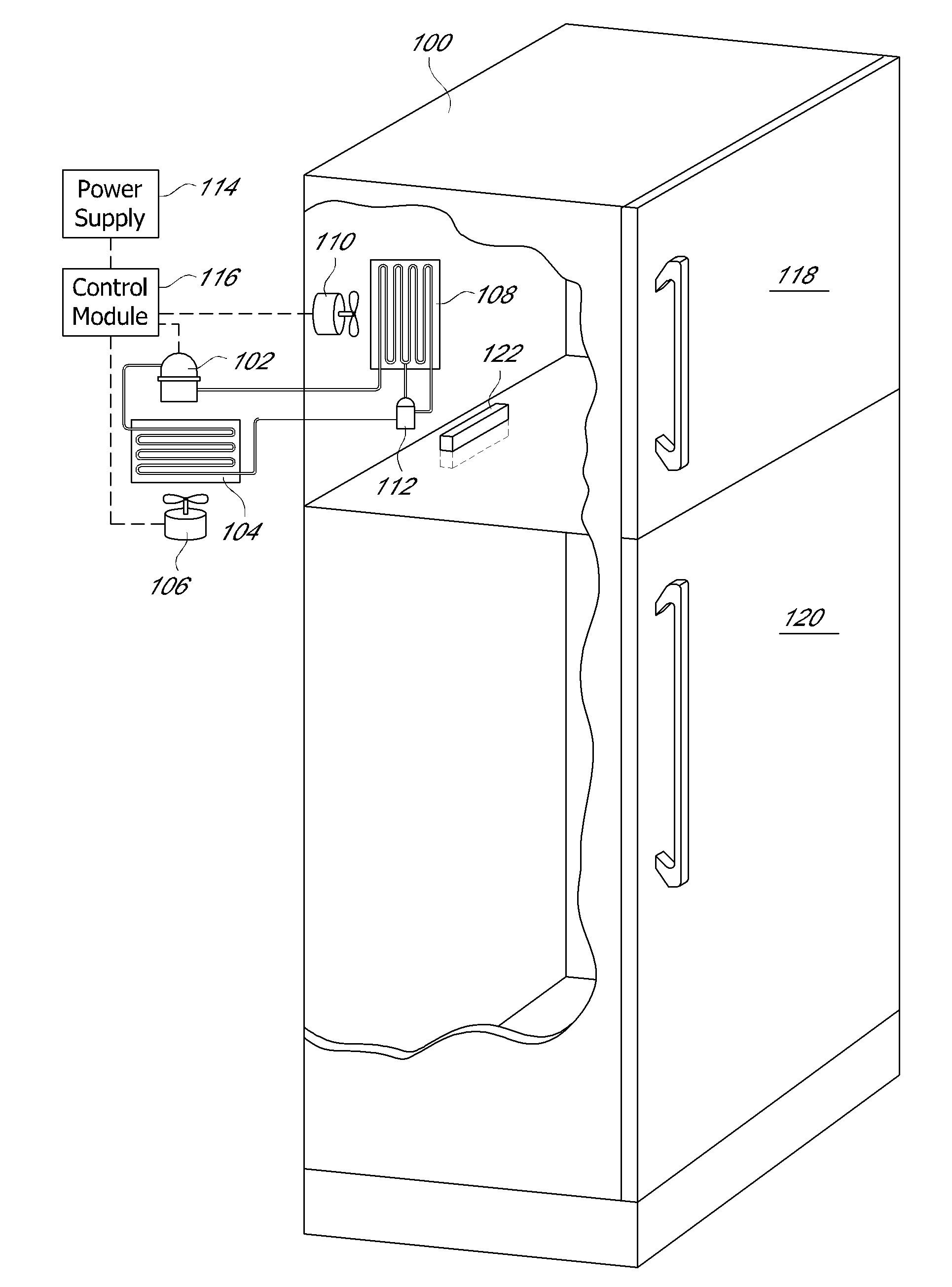
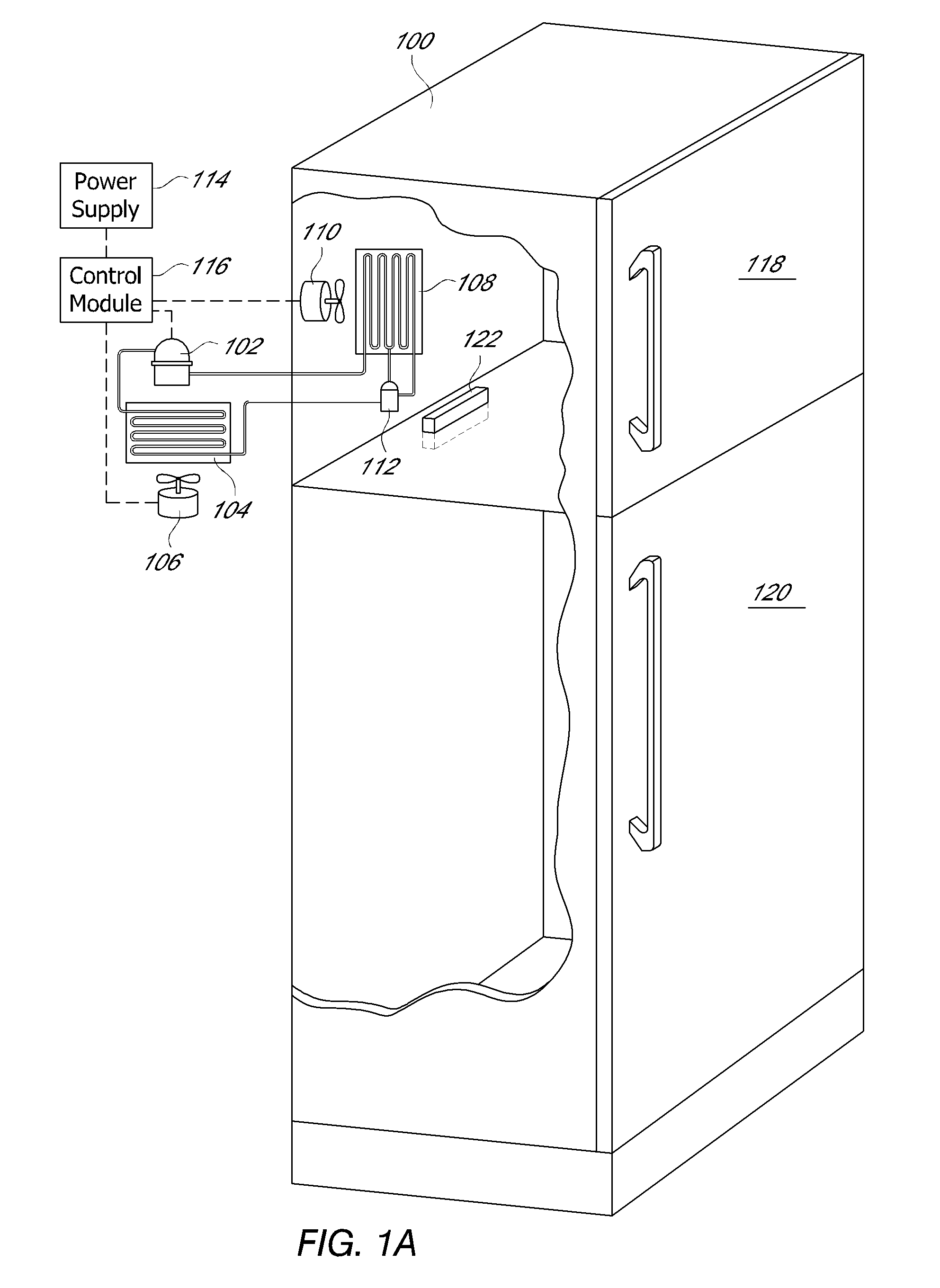
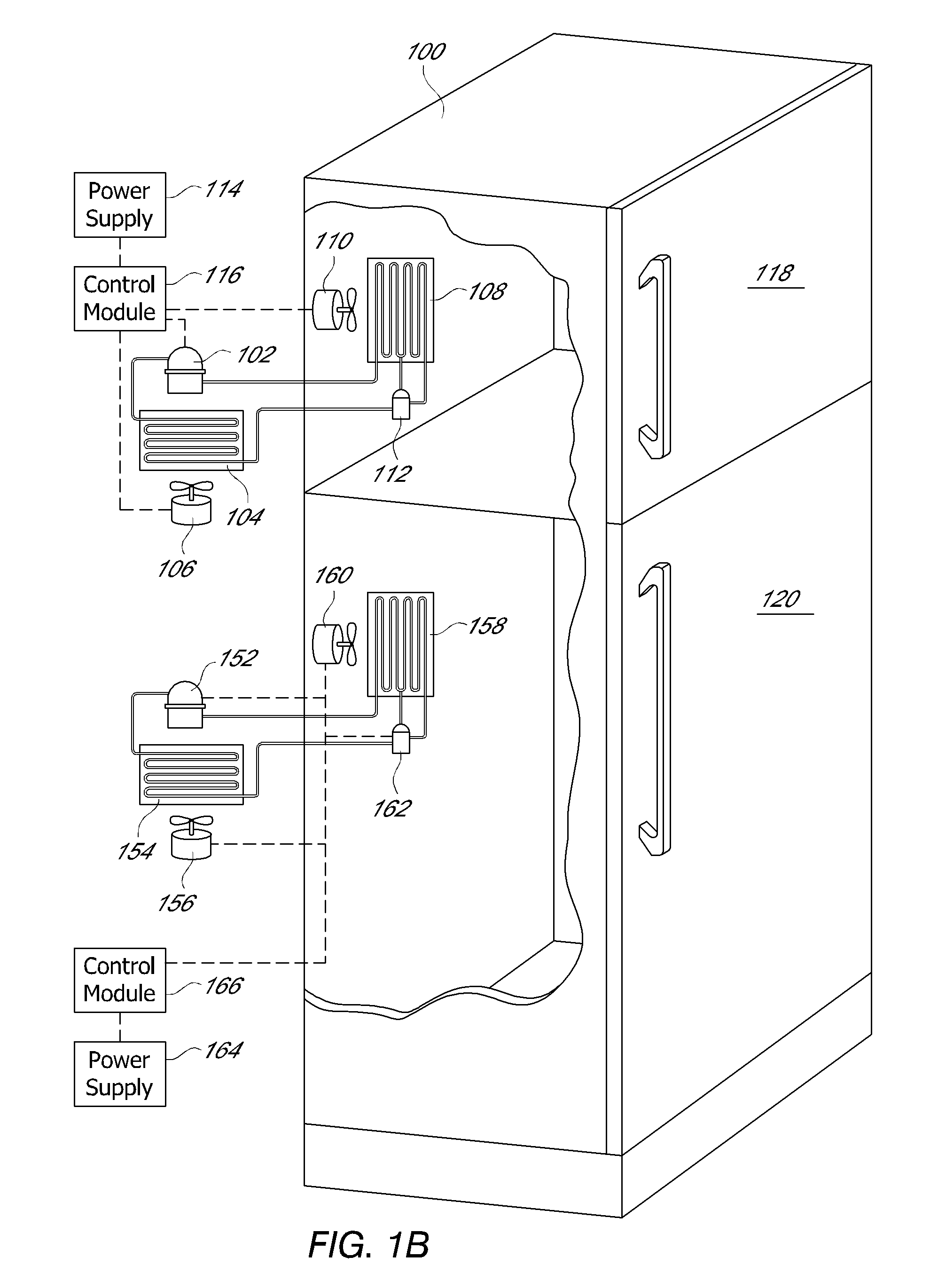
[0031]A refrigerator is an insulated cabinet with an electric compressor which cycles a refrigerant fluid, where by evaporation of refrigerant liquid in the evaporator the refrigerator cools down. When the door is opened, the cold air falls out to be replaced by warm air in the room, which triggers the compressor to start and to circulate the refrigerant liquid and cool down the internal temperature and keep the food safe. The time required to bring the refrigerator internal temperature down to a safe set point is defined as “pull-down”, so faster “pull-down” means shorter period to reach the safe set point temperature. The pull-down is directly related to the refrigerator's ability to cope with the heat loss without food safety risks. It is also directly related to the energy consumption and energy rating of the refrigerator, as fast pull-down results in shorter period the compressor is on and consumes electricity.

[0032]In this e...


PUM


Abstract

A cooling system is disclosed. The cooling system may have an evaporator, an evaporator fan, a condenser, and at least one compressor. The compressor may be either a single speed or a variable speed compressor. In addition, the system can use a mechanical or electrical pulsed operation refrigerant flow control valve for controlling refrigerant flow to the evaporator.

Description

RELATED APPLICATIONS[0001]This application is a continuation-in-part of U.S. patent application Ser. No. 12 / 510,153 filed Jul. 27, 2009 and claims the benefit of U.S. Provisional Patent Application Ser. No. 61 / 436,565 filed Jan. 26, 2011, both of which are hereby incorporated by reference in their entirety.FIELD OF THE INVENTION[0002]This invention relates to cooling systems and more specifically to refrigeration systems.BACKGROUND[0003]Existing cooling systems generally have components including a compressor, a condenser, and an evaporator. In most systems, the compressor motor utilizes the majority of the energy as it starts up in order to provide the proper amount of cooling. However, repeatedly starting and running a compressor motor can be inefficient, because the start-up energy requirements of many compressor motors are high in comparison to the energy required to maintain the motor at a desired speed. In addition, the refrigeration system may not function at peak efficiency ...

Claims


Application Information

Patent Timeline
IPC IPC(8): F25D17/06
CPCH02P1/30H02P1/56H02P1/52H02P1/44F25B49/02F25D17/065F25D19/04F25B2400/06F25B2500/26F25B2600/0253F25B2600/112F25B2600/2513Y02B30/70F25B41/347F25D17/06
Inventor ROCKENFELLER, UWEKHALILI, KAVEH
Owner ROCKY RES
Why Eureka
Try Eureka