
Water Use Monitoring Apparatus

a technology for monitoring apparatus and water use, applied in the direction of temperature measurement in household appliances, instruments, heat measurement, etc., can solve the problems of not being able to wirelessly monitor the primary water meter, not being able to readily locate or not, and not being able to easily monitor the daily, weekly, monthly and annual water use of the reader

Inactive Publication Date: 2011-12-15
KLICPERA MICHAEL
View PDF9 Cites 56 Cited by
  • Summary
  • Abstract
  • Description
  • Claims
  • Application Information

AI Technical Summary

Problems solved by technology

However, the location of the primary water meter is usually not readily available or not in a convenient location for a commercial owner or occupier, or a resident to observe.
Even if the primary water meter is available for review by a commercial owner or occupier, or resident, the display is a simple continuous or cumulative gauge that does not allow the reader to readily monitor their daily, weekly, monthly, and annual water uses.
Furthermore, the primary water meter does not have the capability to wirelessly transfer water use information to a remote display (or recorder with data collection / database) that is conveniently located for review by the owner or occupant of a residence or building to encourage water conservation.
In addition, the primary water meter only monitors commercial or residential supply water, and there is no capability to analyze hot and / or cold water use to provide water energy use information or distinguish between indoor and outdoor water use.

Method used


Image

  • Water Use Monitoring Apparatus
  • Water Use Monitoring Apparatus
  • Water Use Monitoring Apparatus

Examples


Embodiment Construction

[0023]Definitions of word or phrases to be used herein are presented below:

[0024]Water Use refers to the total volume of water used over a period of time.

[0025]Water Energy Use refers to the ratio of cold or ambient water to heated water use or to the ratio of hot water to total water use or as further defined herein.

[0026]Residential and Commercial operations refers to multi-unit apartment buildings, condominiums, hospitals, dormitories, commercial office buildings, homes, and the like.

[0027]Encryption refers to a privacy technology that prevents anyone but the intended recipient(s) to download, review or read confidential information and data.

[0028]Authentication refers to the technology that ensures that a message, data or information that is downloaded or transferred from a one person or device to another declared or intended person or device.

[0029]Integrity refers to technology that ensures that a message, information or data does not alter in any way during transit.

[0030]Non-r...


PUM


Abstract

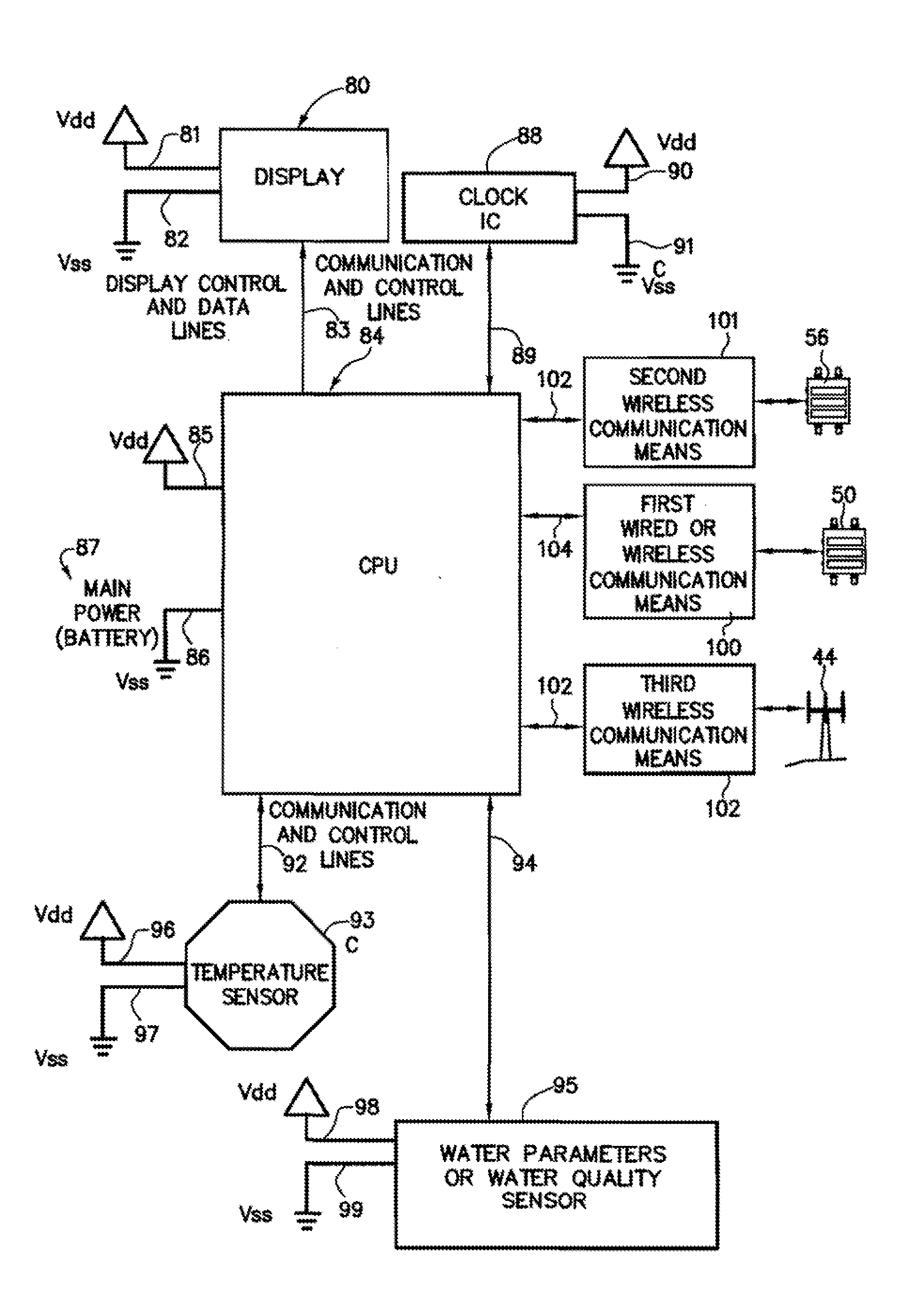
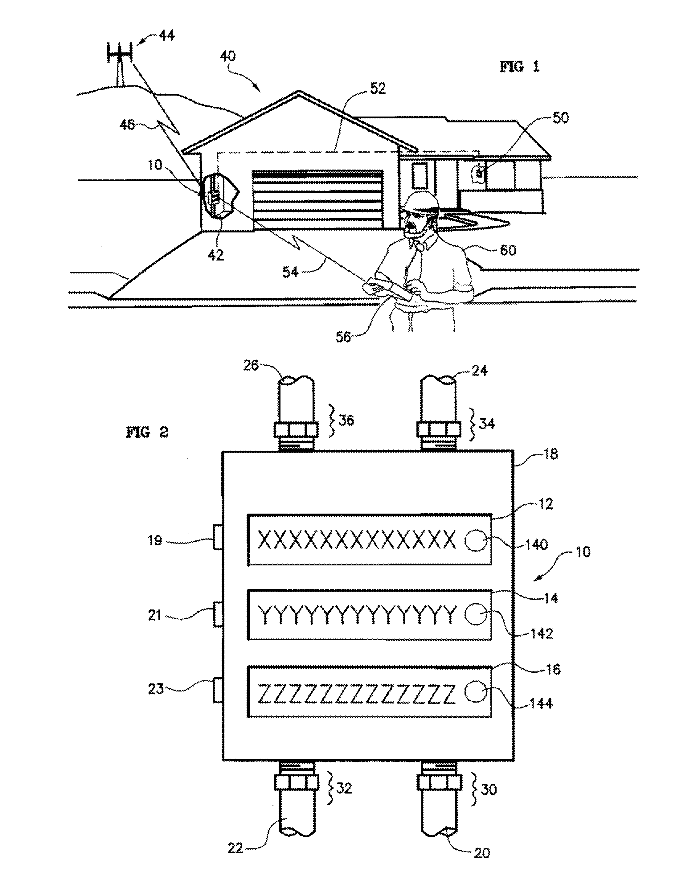
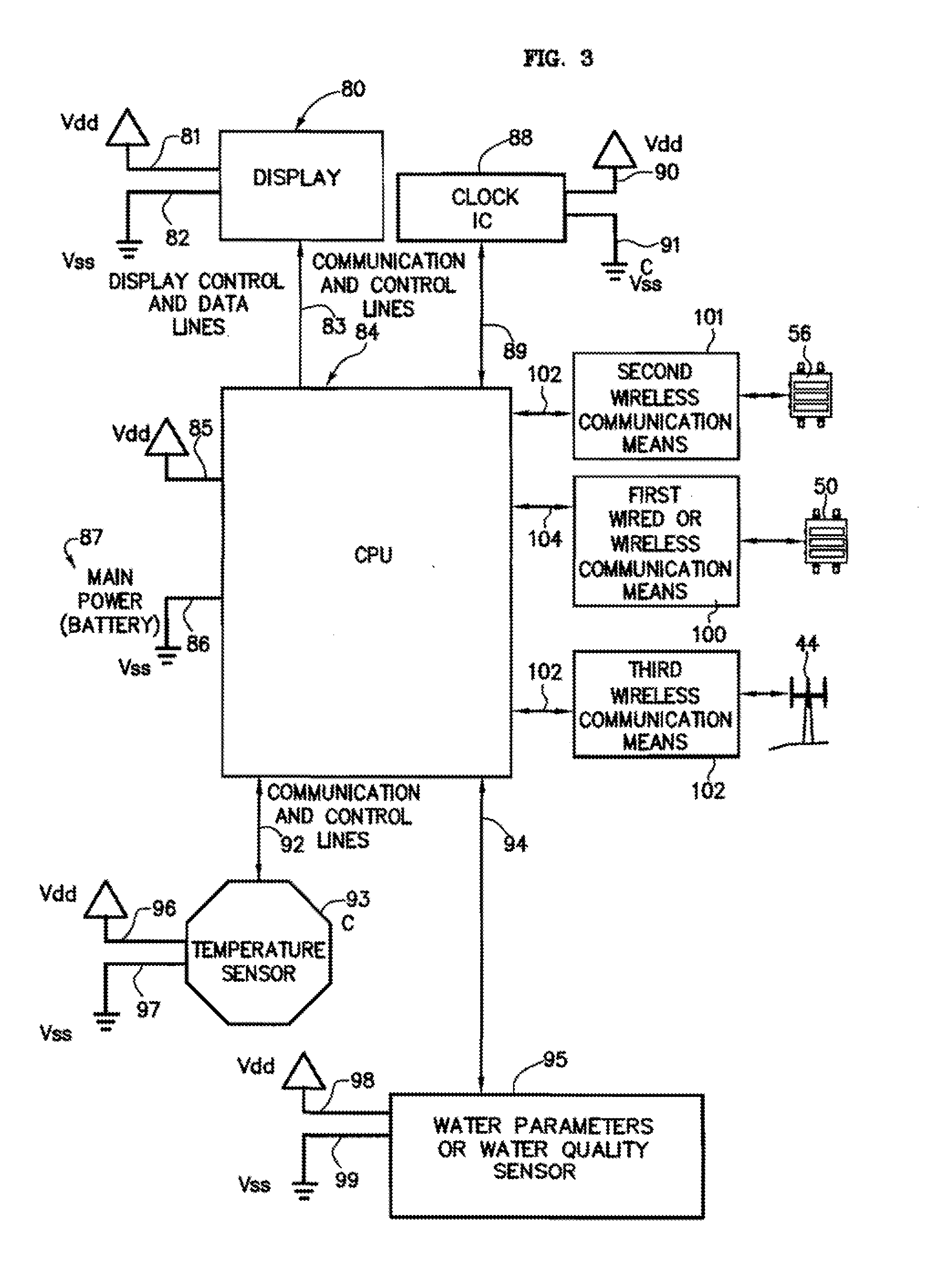
The present invention is a water use and / or a water energy use monitoring apparatus that is affixed to the hot and cold water supply piping for continuously (or on demand) monitoring displaying the water and water energy (hot vs. ambient) use within a residential or commercial building. A first wire or wireless means is incorporated to communicate with a remote display for viewing by the owner of a commercial building or occupier / resident of a home. A second optional wire or wireless means can be incorporated that can be monitored by civil, commercial, governmental or municipal operators or agencies, using a remote display and / or recorder means or by a secure wire or wireless communication network (e.g. cell phone technology communication means). A third wireless means communicates water parameter data utilizing typical cell tower technology and / or mesh network technology. The water use monitor apparatus includes a power generation, a microprocessor, temperature and water flow sensors, optional water quality sensors, timing circuits, wireless circuitry, and a display means. A first wired or wireless means is designed to electronically communicate water use and water energy use information to a remotely located display for convenient observation by a commercial operator or occupier, or resident. An optional second wireless means is designed to electronically communicate water and / or water energy use information to governmental or municipal operators or agencies.

Description

RELATED APPLICATIONS[0001]This application is a continuation-in-part of U.S. application Ser. No. 11 / 877,860 tiled on Oct. 24, 2007, U.S. application Ser. No. 12 / 539,150 filed on Aug. 11, 2009, U.S. application Ser. No. 12 / 877,094 filed on Sep. 7, 2010, and Provisional Patent Application Ser. No. 61 / 389,709 filed on Oct. 4, 2010.FIELD OF THE INVENTION[0002]This apparatus and the method of use relates to a metering apparatus integrated with residential or commercial water supply piping, more particularly, relates to a water use with or without a water energy use monitoring apparatus. This apparatus has the capability of communicating with an optional remote display for viewing and recording within a residential or commercial building, and / or with an optional remote display for viewing or recording for government or municipal purposes.BACKGROUND OF THE INVENTION[0003]Water conservation is becoming a major issue for many cities, towns, and communities, and an apparatus for monitoring w...

Claims


Application Information

Patent Timeline
Patent Type & Authority Applications(United States)
IPC IPC(8): F16K37/00
CPCB05B1/18G10L2015/223B05B12/008B05B12/02B05B12/12E03B7/04E03C1/0408E03C2001/0418G01F15/024G01F15/063G01F15/075G01F15/0755G01K13/02G01K2013/026G01K2207/00G10L15/22B05B12/004Y10T137/8158Y02A20/00G01K13/026
Inventor KLICPERA, MICHAEL
Owner KLICPERA MICHAEL
Learn More