
Liquid crystal display device associated with touch panel and method for fabricating the same

a technology of touch panel and display device, which is applied in the manufacture of electrode systems, electric discharge tubes/lamps, instruments, etc., can solve the problems of poor transmissivity, material is required, poor touch sensitivity, etc., and achieve the effect of improving the touch sensitivity of the user

Active Publication Date: 2011-12-15
LG DISPLAY CO LTD
View PDF11 Cites 85 Cited by
  • Summary
  • Abstract
  • Description
  • Claims
  • Application Information

AI Technical Summary

Benefits of technology

[0030]An object of the present invention is to provide a liquid crystal display device associated with a touch panel, in which driving electrodes are formed on an outer surface of a color filter substrate of a liquid crystal panel by patterning for cutting off noise from the liquid crystal panel and fabricating slimmer and more integrated device.
[0038]And, the device can further include a protective film on the third substrate. The protective film can be a glass substrate or an insulating transparent film for improving a touch sensitivity of the user and protecting underlying electrodes.

Problems solved by technology

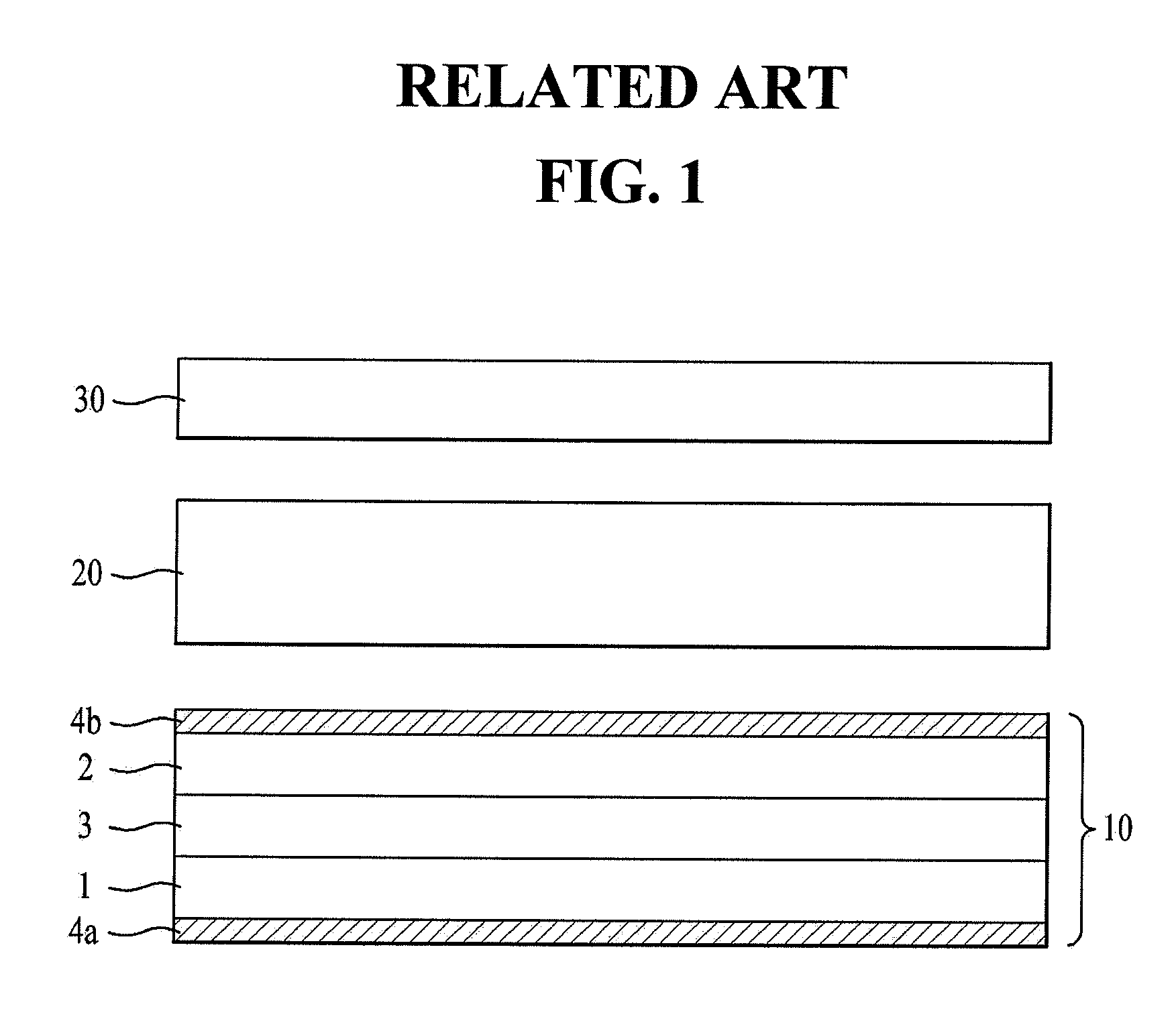
However, the related art touch panel attached type liquid crystal display device has the following problems.
Along with this, the disposition of the shielding transparent electrode between the liquid crystal panel 10 and the touch panel 20 causes transmissivity poor.
In this case, patterning of the insulating film on a backside of the touch panel glass substrate is also required for application of a signal, to cause problems in that additional steps, and material are required, and transmissivity becomes poor.
And, in a case the electrodes are formed on both sides of the touch panel glass substrate, the touch panel glass substrate is required to turn over for performing required steps, causing problems in that a process time period is increased, and defects, such as scratch or formation of foreign matter, increases.

Method used


Image

  • Liquid crystal display device associated with touch panel and method for fabricating the same
  • Liquid crystal display device associated with touch panel and method for fabricating the same
  • Liquid crystal display device associated with touch panel and method for fabricating the same

Examples


Embodiment Construction

[0054]Reference will now be made in detail to the specific embodiments of the present invention, examples of which are illustrated in the accompanying drawings. Wherever possible, the same reference numbers will be used throughout the drawings to refer to the same or like parts.

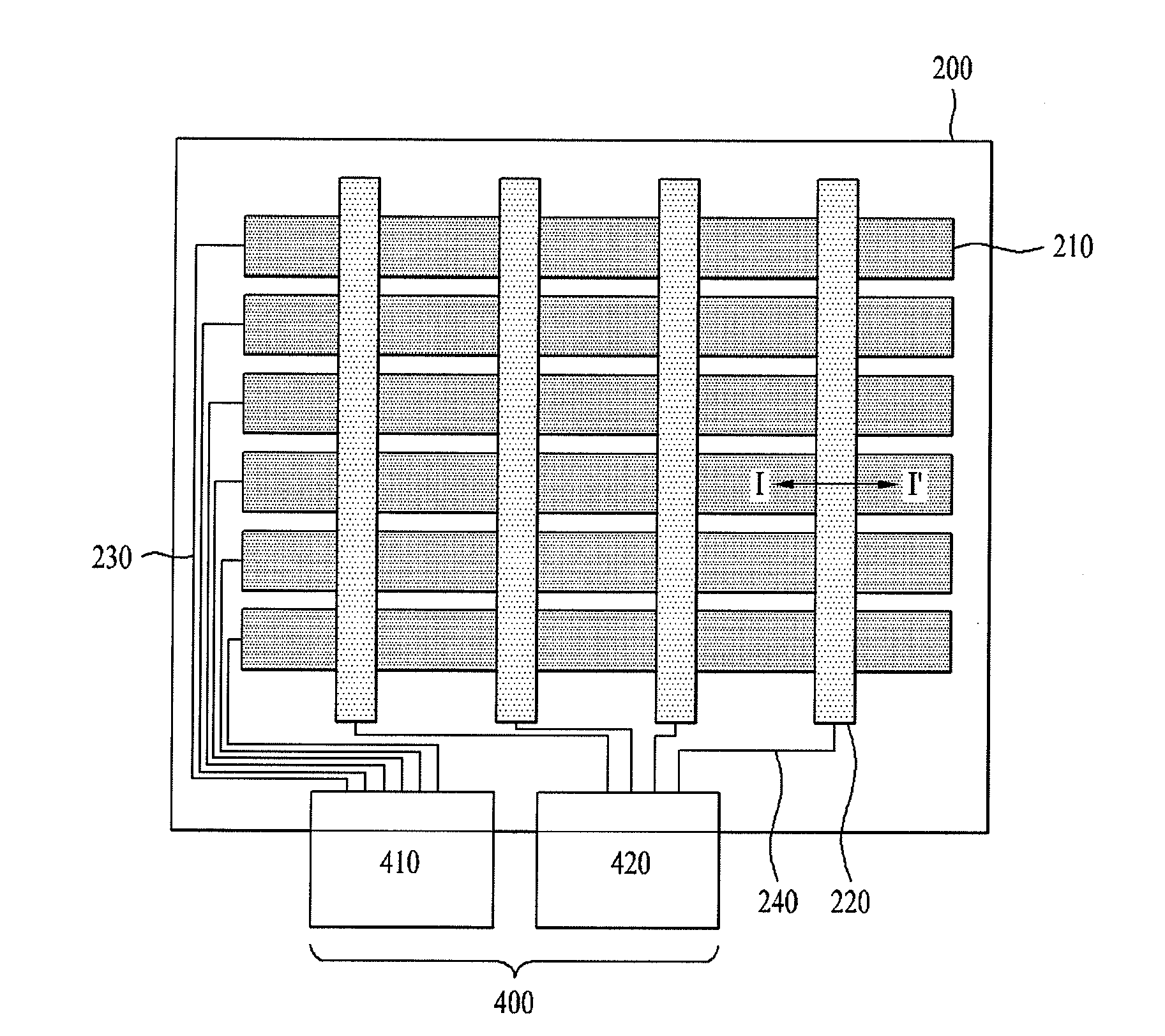
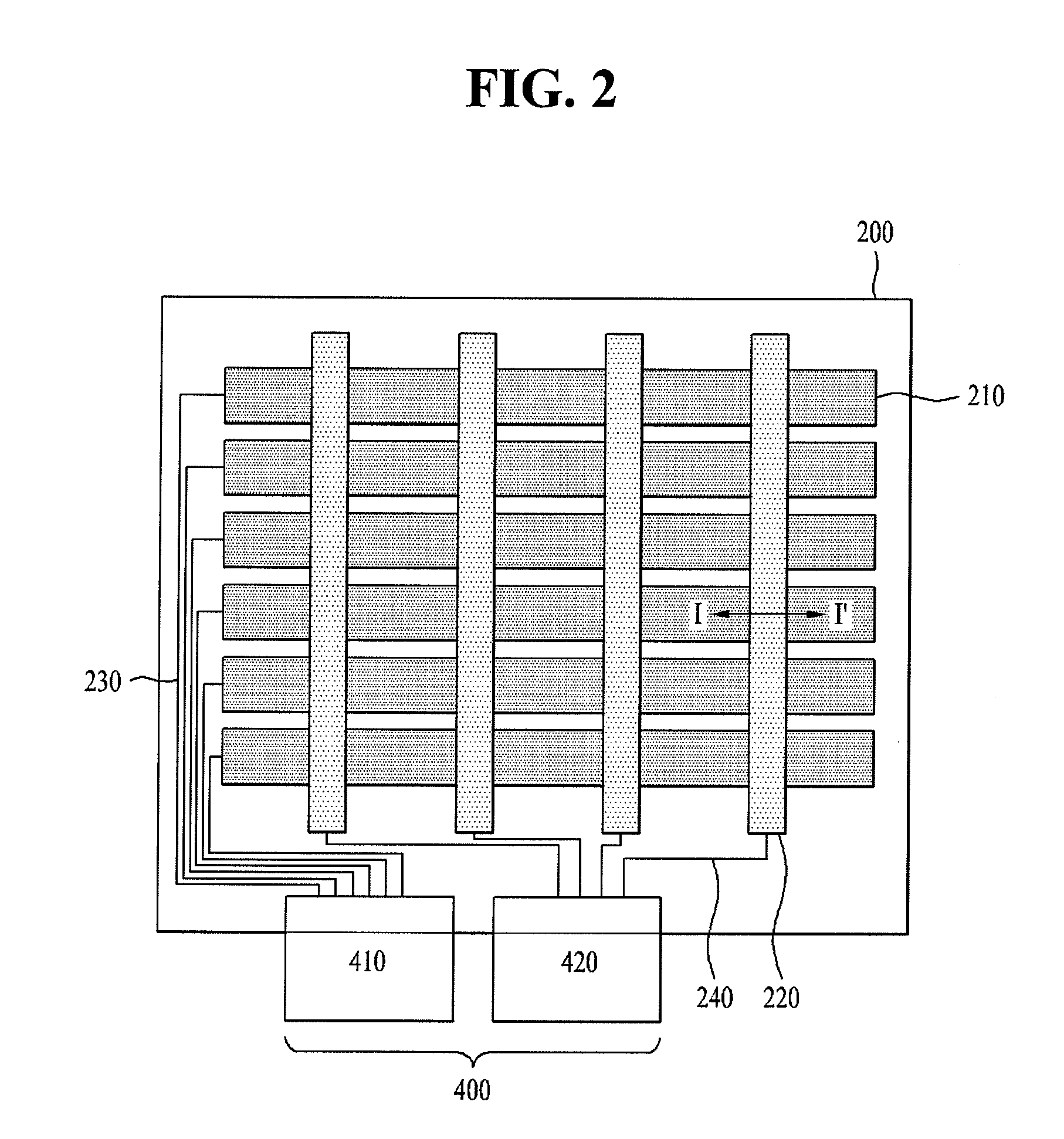
[0055]FIG. 2 illustrates a plan view of a liquid crystal display device associated with a touch panel in accordance with a preferred embodiment of the present invention, and FIG. 3 illustrates a schematic view of FIG. 2.

[0056]Referring to FIGS. 2 and 3, the liquid crystal display device associated with a touch panel includes a liquid crystal panel 800 having a thin film transistor substrate 100 and a color filter array substrate 200 opposite to each other, and a liquid crystal layer 150 formed between the thin film transistor substrate 100 and the color filter array substrate 200, a plurality of driving electrodes 210 formed on a back side of the color filter array substrate 200 of the liquid crystal panel 80...


PUM


Abstract

The present invention relates to a liquid crystal display device associated with a touch panel, the device includes a liquid crystal panel having opposite first and second substrates, and a liquid crystal layer formed between the first and second substrates, a plurality of driving electrodes arranged on an outer surface of the second substrate in one direction spaced from one another, a first polarizing plate formed on the outer surface of the second substrate including the driving electrodes, a third substrate opposite to the first polarizing plate, and a plurality of sensing electrodes formed on a surface of the third substrate opposite to the first polarizing plate perpendicular to the driving electrodes spaced from one another.

Description

CROSS REFERENCE TO RELATED APPLICATION[0001]This application claims the benefit of the Korean Patent Application No. 10-2010-0054967, filed on Jun. 10, 2010, which is hereby incorporated by reference as if fully set forth herein.BACKGROUND OF THE DISCLOSURE[0002]1. Field of the Disclosure[0003]The present invention relates to liquid crystal display devices, and more particularly to a liquid crystal display device associated with a touch panel, in which driving electrodes are formed on an outer surface of a color filter substrate of a liquid crystal panel by patterning for cutting off noise from the liquid crystal panel and fabricating slimmer and more integrated device.[0004]1. Discussion of the Related Art[0005]Currently, as the time turns into a full scale information oriented time, a display field in which an electric information signal is expressed in a visual sensation has been developed rapidly, and, meeting to this development, various kinds of flat display devices have been ...

Claims


Application Information

Patent Timeline
Patent Type & Authority Applications(United States)
IPC IPC(8): G06F3/041H01J9/24
CPCG02F1/13338G06F2203/04103G06F3/044G06F3/0412G06F3/0446G06F3/0445G02F1/1362G02F1/133512G02F1/133514
Inventor KIM, TAE-HWANKIM, TAE-HOON
Owner LG DISPLAY CO LTD
Learn More