Touch panel

a technology of touch panel and carbon nanotube, which is applied in the field of touch panel, can solve the problems of resistive touch panel not being able to detect capacitive signals, resistive touch panel is slow reaction speed and low sensitivity,

Active Publication Date: 2011-12-15
BEIJING FUNATE INNOVATION TECH
View PDF5 Cites 35 Cited by
  • Summary
  • Abstract
  • Description
  • Claims
  • Application Information

AI Technical Summary

Benefits of technology

[0006]A resistive touch panel often includes two layers of transparent conductive layers positioned apart from each other by a plurality of spacers. If one user presses the touch panel with a finger, pressure from the touch will cause the two transparent conductive layers to electrically contact each other at the pressing point, and the location of the pressing point can be calculated. The resistive touch panel has high definition and a long lifetime. However, the resistive touch panel cannot detect capacitive signals and cannot detect the touching signals until the pressure at the pressing point is great enough to force the two transparent conductive layers to contact each other. As such, the resistive touch panel has a slow reaction speed and low sensitivity.

Problems solved by technology

However, the resistive touch panel cannot detect capacitive signals and cannot detect the touching signals until the pressure at the pressing point is great enough to force the two transparent conductive layers to contact each other.
As such, the resistive touch panel has a slow reaction speed and low sensitivity.

Method used


Image

  • Touch panel
  • Touch panel
  • Touch panel

Examples


Embodiment Construction

[0016]The disclosure is illustrated by way of example and not by way of limitation in the figures of the accompanying drawings in which like references indicate similar elements. It should be noted that references to “an” or “one” embodiment in this disclosure are not necessarily to the same embodiment, and such references mean at least one.

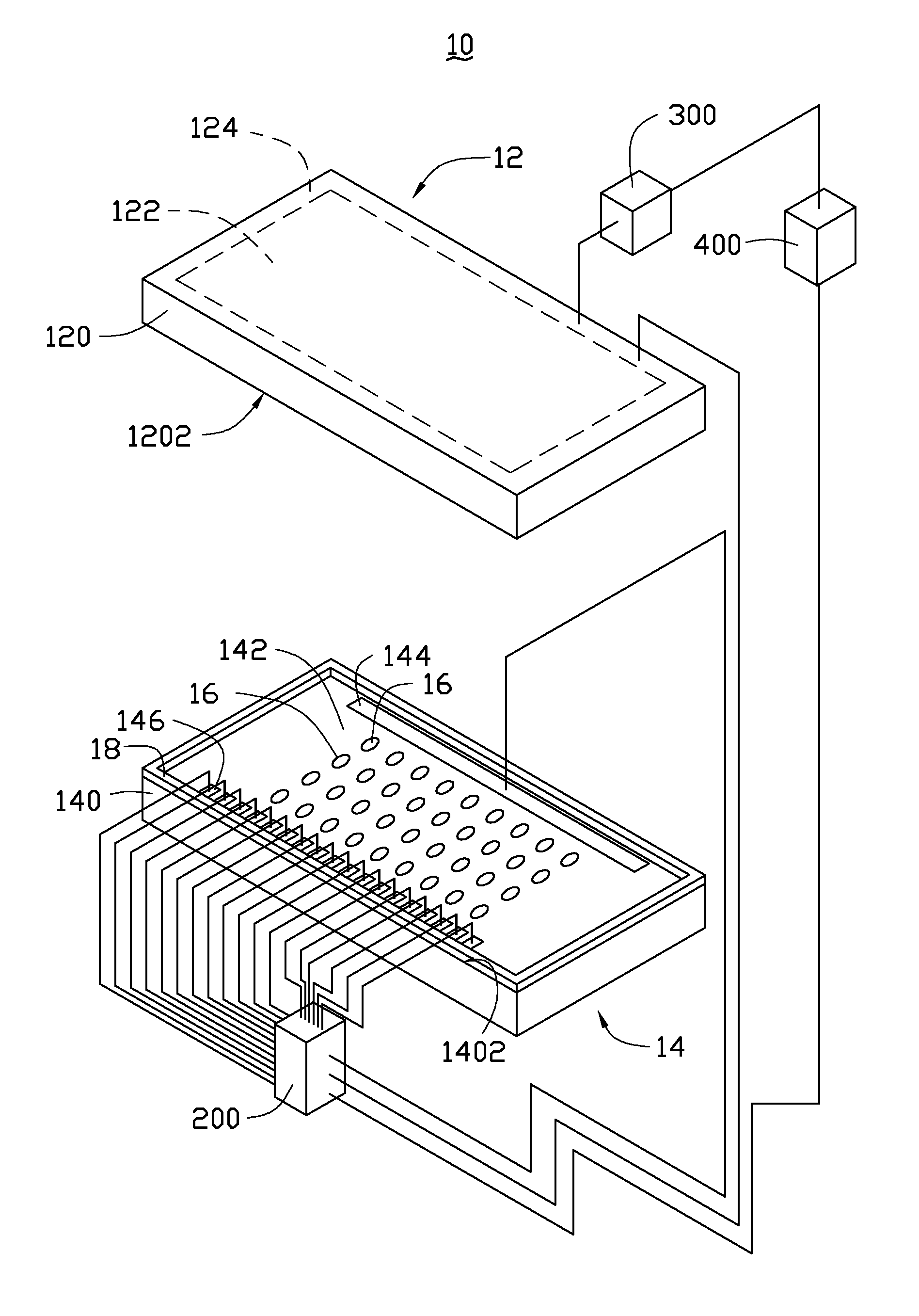
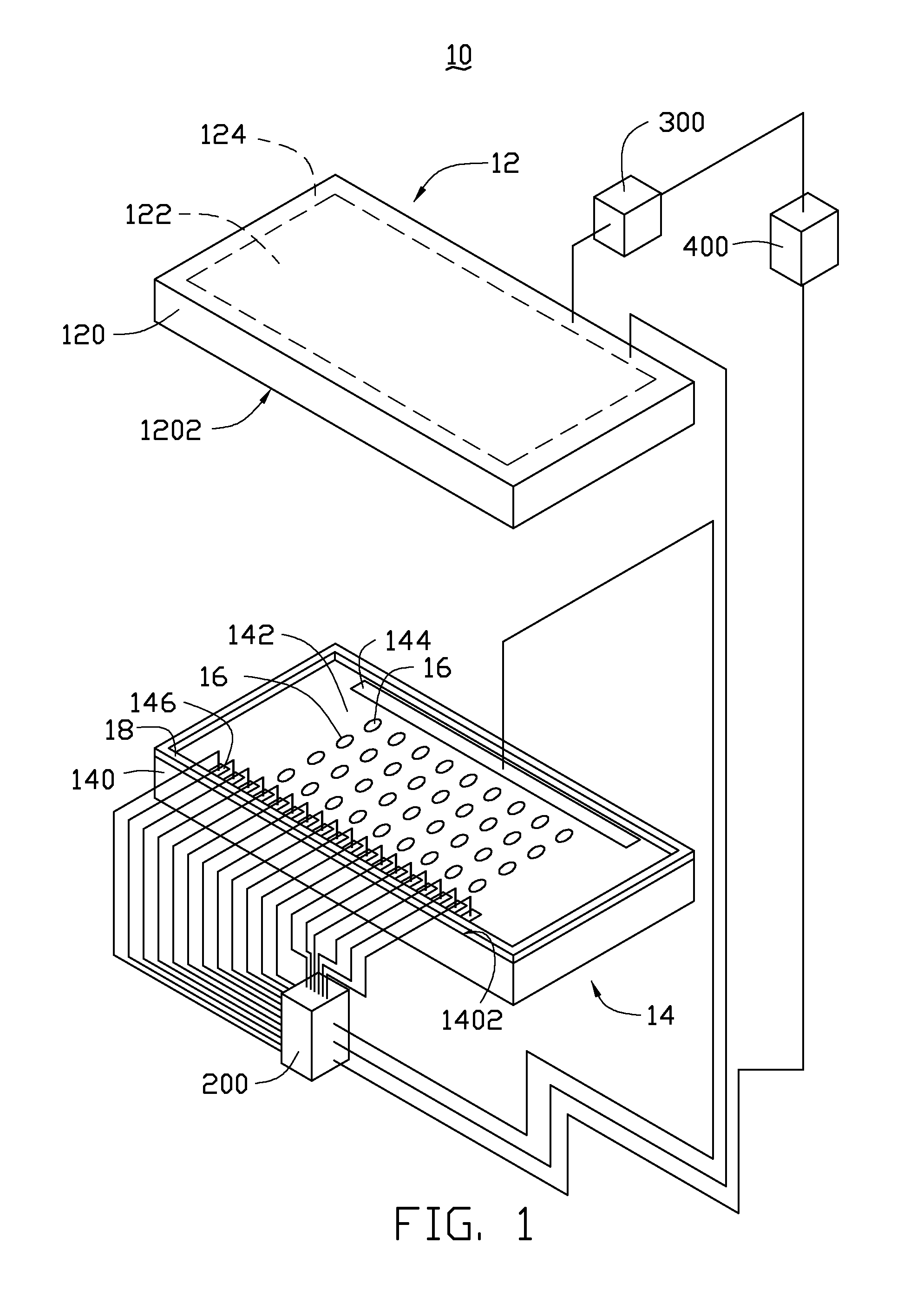
[0017]Referring to FIG. 1 and FIG. 2, one embodiment of a touch panel 10 comprises a first electrode plate 12, a second electrode plate 14, a plurality of transparent dot spacers 16, a resistive touch panel detector 200, a capacitive detector 300, and a processor 400. The resistive touch panel detector 200 is electrically connected to the first electrode plate 12 and the second electrode plate 14. The capacitive detector 300 and the resistive touch panel detector 200 are selected to perform work in response to force applied on the first electrode plate 12. The resistive touch panel detector 200 responds to voltage changes between the first electr...


PUM


Abstract

A touch panel includes a first electrode plate, a second electrode plate, and a capacitive detector. The first electrode plate includes a first transparent conductive layer. The second electrode plate includes a second transparent conductive layer opposite to and spaced from the first transparent conductive layer. The second transparent conductive layer is a conductive film having different resistance along different directions. The capacitive detector is electrically connected with the first electrode plate.

Description

RELATED APPLICATIONS[0001]This application claims all benefits accruing under 35 U.S.C. §119 from China Patent Application No. 201010198630.6, filed on Jun. 1, 2010, in the China Intellectual Property Office, the disclosure of which is incorporated herein by reference.BACKGROUND[0002]1. Technical Field[0003]The disclosure relates to touch panels and, particularly, to a carbon nanotube-based touch panel.[0004]2. Description of Related Art[0005]Various electronic apparatuses such as mobile phones, car navigation systems, and the like, are equipped with optically transparent touch panels applied over display devices such as liquid crystal panels. The electronic apparatus is operated when contact is made with the touch panel corresponding to elements appearing on the display device. A demand thus exists for such touch panels to maximize visibility and reliability in operation.[0006]A resistive touch panel often includes two layers of transparent conductive layers positioned apart from e...

Claims


Application Information

Patent Timeline
Patent Type & Authority Applications(United States)
IPC IPC(8): G06F3/045G06F3/044B82Y99/00
CPCG06F3/044G06F2203/04106G06F3/045G06F3/0445G06F3/0446
Inventor FENG, CHENQIAN, LILIU, LIANG
Owner BEIJING FUNATE INNOVATION TECH
Why Eureka
Try Eureka