Stereoscopic image display device and stereoscopic image display method
a stereoscopic image and display device technology, applied in the field of stereoscopic image display methods, can solve the problems of increasing system size, complicated control, and stereoscopic image display devices according to the previous methods
Inactive Publication Date: 2011-12-15
SONY CORP
View PDF38 Cites 16 Cited by
- Summary
- Abstract
- Description
- Claims
- Application Information
AI Technical Summary
Benefits of technology
The invention provides a stereoscopic image display device and method that can be viewed from multiple angles and can display different content to different observers. The device includes a cylindrical rotation section with a light-emission element array mounted inside it. The light-emission elements are controlled to emit light through a slit in the rotation section, allowing for the display of a stereoscopic image around the rotation center. The device also includes an eyepoint detection section to detect the position of the observer's eyes, and the display controller controls the light-emission elements to change the content of the displayed image based on the observer's position. This allows for a more realistic and immersive viewing experience for the observer.
Problems solved by technology
The stereoscopic image display devices according to the previous methods have the following difficulties.
The stereoscopic picture display device according to the non-patent document 1 needs to have the view-angle limiting screen, the rotation mechanism, the upper mirror, the lower mirror group, the projector and the personal computer, which increases system size, leading to complicated control.
Since beams from the plurality of pixels on the display surface are allocated to the respective openings or lenses, practical image quality is hard to be obtained.
Method used
View moreImage
Smart ImageViewing Examples


Examples
seventh embodiment (
7. Seventh embodiment (optimization of slit width).
eighth embodiment (
8. Eighth embodiment (optimization of light emitting timing).
ninth embodiment (viewing example of stereoscopic image using each of display devices according to first to eighth embodiments)
9.
10. Tenth embodiment (omnidirectional stereoscopic image display device 70: configuration example and operation example).
11. Eleventh embodiment (omnidirectional stereoscopic image display device 80: configuration example and operation example).
Login to View More PUM
 Abstract
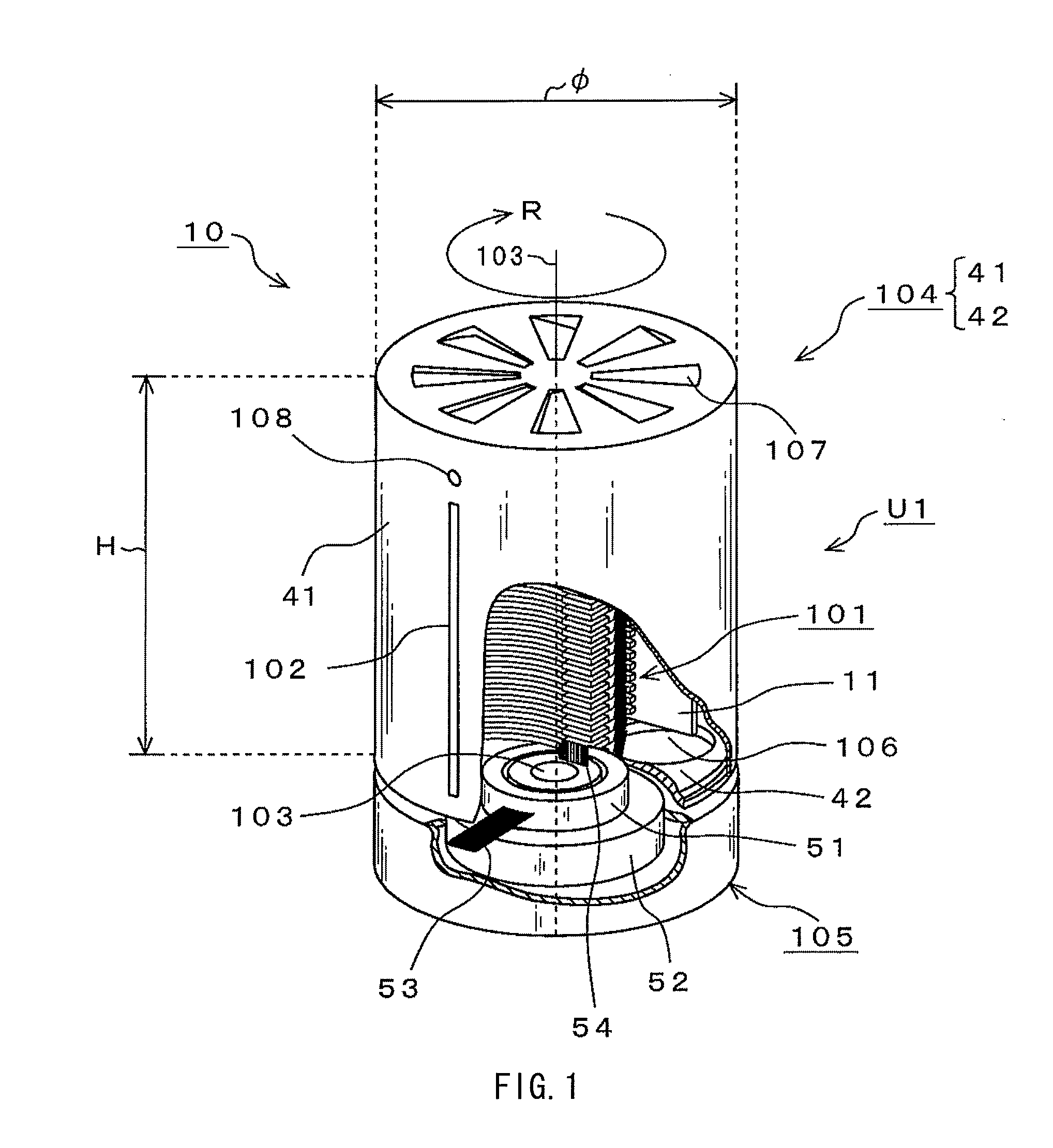
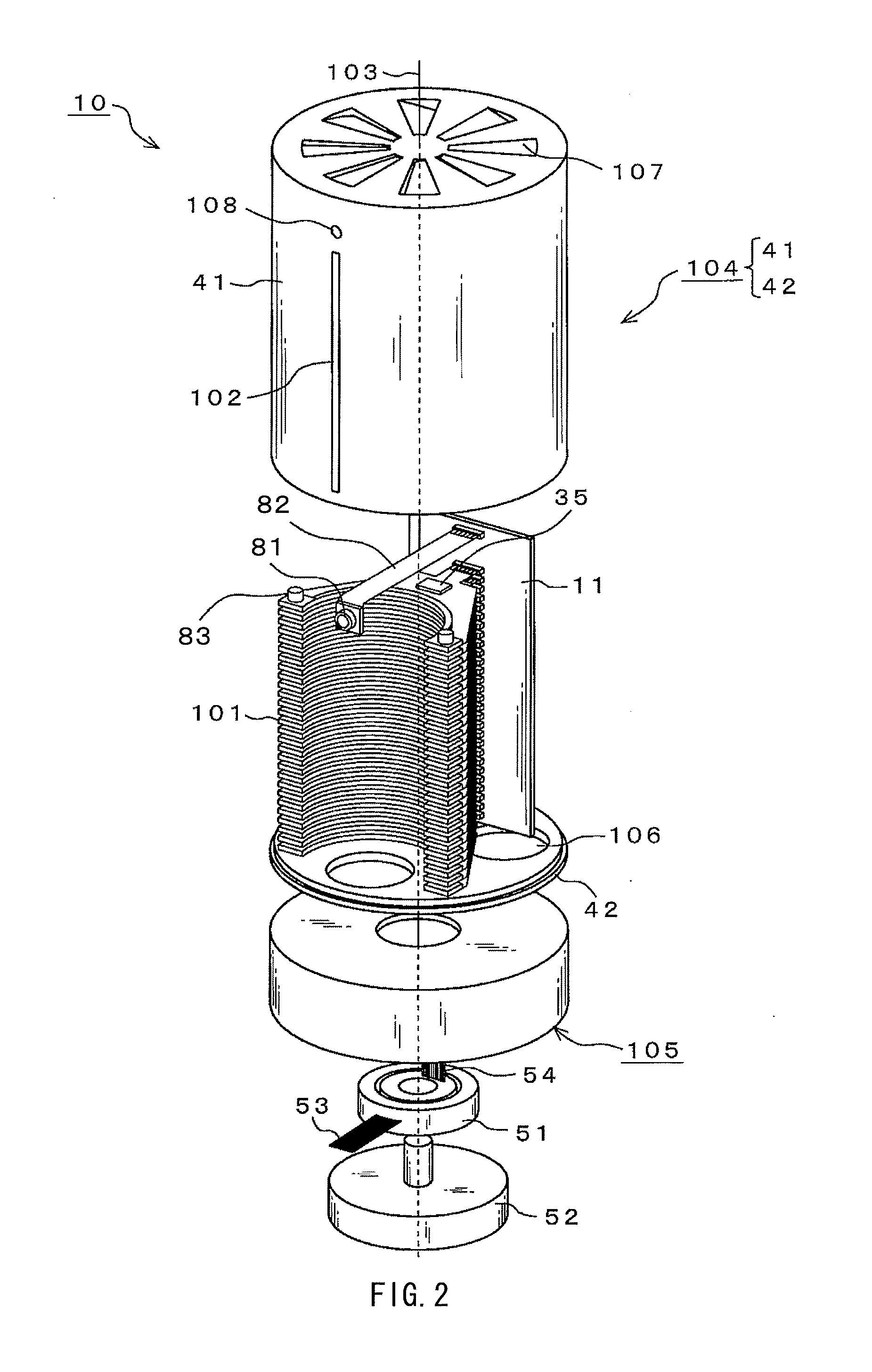
A display device includes: a cylindrical rotation section having an axis of rotation therein and rotating around the axis of rotation; a light-emission element array mounted in the rotation section, and including light-emission elements arranged to formed a light-emission surface; a slit provided in a circumferential surface of the rotation section, and allowing light from the light-emission surface to pass therethrough to outside of the rotation section; a display controller performing emission control on the light-emission elements to allow an image to be formed by the light emitted through the slit and to be displayed around the rotation section; and an eyepoint detection section detecting an eyepoint position of each of one or more viewers around the rotation section. The display controller performs emission control on the light-emission elements to allow contents of a displayed image to differ depending on the viewer's eyepoint position detected by the eyepoint detection section.
Description
BACKGROUND OF THE INVENTION1. Field of the InventionThe present invention relates to a stereoscopic image display device and a stereoscopic image display method, which may display a stereoscopic image over the entire circumference.2. Description of Related ArtMany proposals have been made so far on an omnidirectional stereoscopic image display device of an integral imaging method, which reproduces a stereoscopic image over the entire circumference of an object based on two-dimensional picture data for stereoscopic image display obtained by taking images of the object over the entire circumference or creating such images by a computer. For example, “Stereoscopic Image Display Device Observable from All Directions” (URL: http: / / hhil.hitachi.co.jp / products / transpost.html) (non-patent document 1) discloses a stereoscopic picture display device observable from all directions. The stereoscopic picture display device has a view-angle limiter screen, a rotation mechanism, an upper mirror, a...
Claims
Login to View More Application Information
Patent Timeline
 Patent Type & Authority Applications(United States)
IPC IPC(8): G06T15/00G03B35/18
CPCG02B27/0093H04N13/0477H04N13/0409G02B27/225H04N13/376H04N13/31
Inventor YASUNAGA, HIROAKI
Owner SONY CORP
Features
- R&D
- Intellectual Property
- Life Sciences
- Materials
- Tech Scout
- Unparalleled Data Quality
- Higher Quality Content
- 60% Fewer Hallucinations
Learn More Browse by: Latest US Patents, China's latest patents, Technical Efficacy Thesaurus, Application Domain, Technology Topic, Popular Technical Reports.
© 2025 PatSnap. All rights reserved.Legal|Privacy policy|Modern Slavery Act Transparency Statement|Sitemap|About US| Contact US: help@patsnap.com