Time-of-flight imager

a time-of-flight imager and time-of-flight imaging technology, applied in the field of time-of-flight imager and time-of-flight imaging method, can solve the problems of unsatisfactory depth maps and pulse propagation delay across the array, and achieve the effect of improving accuracy

Active Publication Date: 2011-12-15
INTERDIGITAL CE PATENT HLDG
View PDF30 Cites 54 Cited by
  • Summary
  • Abstract
  • Description
  • Claims
  • Application Information

AI Technical Summary

Benefits of technology

[0005]Accordingly, it is an object of the present invention to propose a solution for time-of-flight generation of depth maps, which achieves an improved accuracy.

Problems solved by technology

Despite a minute control of the temporal relations between the light source, the transfer gate and the global shutter gate pulse, especially for sensors with a large number of pixels the measured depth maps are not satisfactory.
However, the temporal relation of these pulses with regard to the light source trigger pulse varies across the array of pixels of the sensor, i.e. the pulses are subject to a propagation delay across the array of pixels.

Method used


Image

  • Time-of-flight imager
  • Time-of-flight imager
  • Time-of-flight imager

Examples


Embodiment Construction

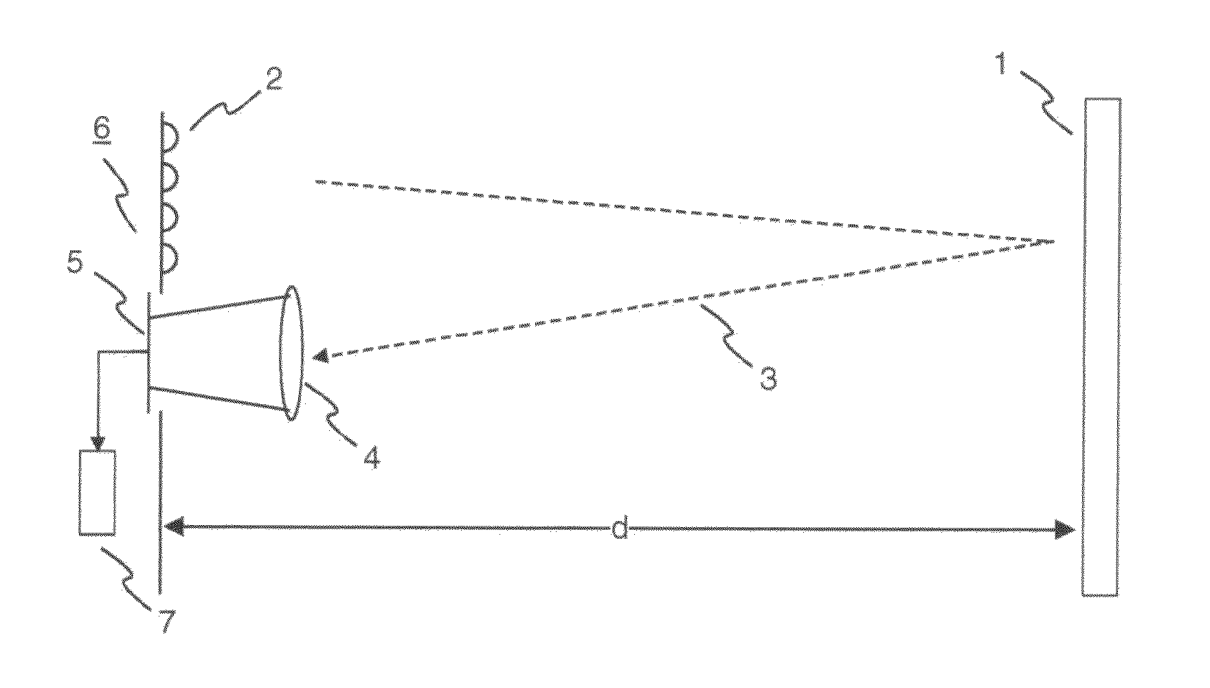
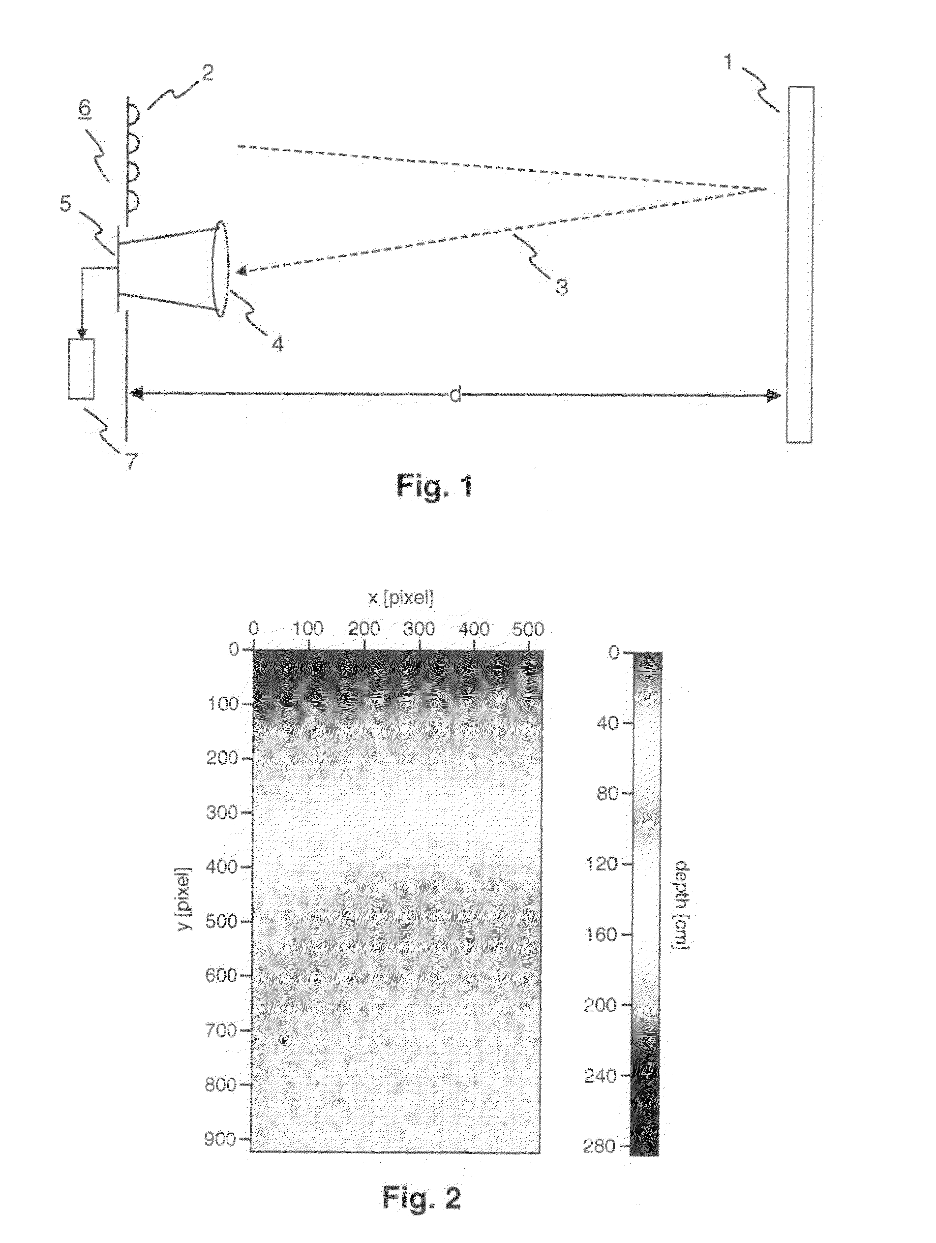
[0040]FIG. 1 illustrates the principle of a time-of-flight imager 6 according to the invention. The time-of-flight imager 6 includes a light source 2, a lens 4, a sensor 5, and processing circuitry 7. An object 1 located at a distance d of 75 cm from the time-of-flight imager 6 is illuminated by the light source 2, e.g. a 4×4 array of infrared LEDs. The object 1 has a flat surface facing an array of pixels of the sensor 5. The light 3 reflected by this flat surface is collected by the lens 4 and imaged onto the array of pixels of sensor 5. This allows to measure a depth map of the object 1. The processing circuitry 7 enables processing of the measured depth map.

[0041]The depth map of the object 1 measured by the time-of-flight imager 6 is shown in FIG. 2. The grey values indicate the measured depth in cm. They are plotted against the pixels of the sensor 5 in x- and y-direction. Though the flat surface of the object 1 has a fixed distance d of 75 cm from the plane of the sensor 5, t...


PUM


Abstract

An improved solution for generating depth maps using time-of-flight measurements is described, more specifically a time-of-flight imager and a time-of-flight imaging method with an improved accuracy. A depth correction profile is applied to the measured depth maps, which takes into account propagation delays within an array of pixels of a sensor of the time-of-flight imager.

Description

FIELD OF THE INVENTION[0001]The present invention relates to an improved solution for generating depth maps using time-of-flight measurements, and more specifically to a time-of-flight imager and a time-of-flight imaging method with an improved accuracy.BACKGROUND OF THE INVENTION[0002]For the generation of 3D video content it is important to measure the distance of objects located in a scene that is being captured in addition to the usual video data. For this purpose a so-called depth map is determined. Typically a time-of-flight imager is used for this purpose, i.e. a measurement system that creates distance data with help of the time-of-flight principle. The time-of-flight imager includes a light source and a light sensor, which consists of an array of pixels. To measure a depth map, the light source is triggered with a pulse, and all pixels of the sensor are simultaneously triggered with a Transfer Gate (TG) pulse and a Global Shutter Gate (GSG) pulse. For details see K. Fife et...

Claims


Application Information

Patent Timeline
Patent Type & Authority Applications(United States)
IPC IPC(8): H04N13/02G01S17/894
CPCG01S17/89G01S7/497G01S17/894G01S7/487G01S17/08
Inventor CENTEN, PETERDAMSTRA, KLAAS JANROTTE, JEROENDEN HEIJKANT, JUUL VAN
Owner INTERDIGITAL CE PATENT HLDG
Why Eureka
Try Eureka