Area light source device and stereoscopic display device
- Summary
- Abstract
- Description
- Claims
- Application Information
AI Technical Summary
Benefits of technology
Problems solved by technology
Method used
Image

Examples
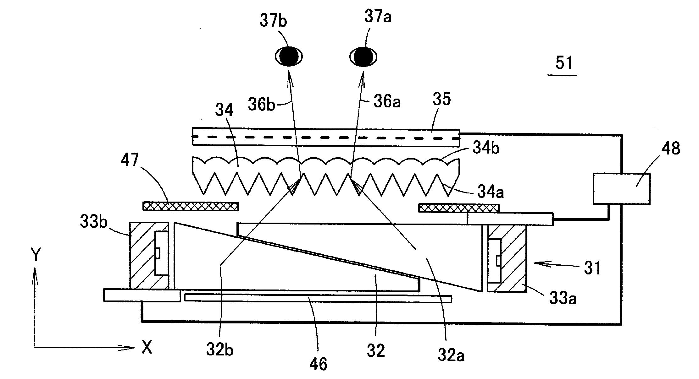
first embodiment
Variant of First Embodiment
[0071]FIGS. 10A to 10C are views showing a variant of the first embodiment of the present invention. In the figures, the end face 38b of the light guide plates 32a, 32b is inclined so as to be non-parallel with respect to the end face 38a.
[0072]In the area light source device of FIG. 10A, the end face 38b of the light guide plate 32a is inclined to become farther away from the end face 38a towards the front side (towards liquid crystal panel). Therefore, the light guided through the light guide plate 32a and reached the end face 38b is totally reflected at the end face 38b and is less likely to return in an original direction, and is easily exit to the outside of the light guide plate 32a by being totally reflected at the end face 38b or by transmitting through the end face 38b. The end face 38b of the light guide plate 32b is also inclined to become farther away from the end face 38a towards the front side. Therefore, the light guided through the light g...
second embodiment
Variant of Second Embodiment
[0082]FIG. 13 is a perspective view showing another example of the light guide plate 32a (or light guide plate 32b) used in the area light source device 61 of the second embodiment. In FIG. 13, the cross-section of a V groove 66 is also shown. In the light guide plate 32a (or light guide plate 32b) of FIG. 13, a plurality of microscopic V grooves 66 is arrayed in parallel and continuously to each other along the inclined surface 65 of the light transitioning unit 64. When such light guide plate 32a, 32b is used, the light that entered to the inclined surface 65 from the light introducing unit 62 can be regressively reflected by the V groove 66, and hence the light that leaks from the inclined surface 65 in the middle of guiding the light that entered the light introducing unit 62 to the light guide plate main body 63 can be reduced, and the light usage efficiency can be enhanced. The luminance of the area light source device 61 thus can be enhanced.
[0083]...
third embodiment
[0086]FIG. 16 is a schematic cross-sectional view showing an area light source device 71 according to a third embodiment of the present invention. Even in such area light source device 71, the light guide plate 32a and the light guide plate 32b are overlapped to form the light guide body 32 as shown in FIG. 12, 13, 14 or 15. However, in the area light source device 71, the flat surface 45a of the light guide plate 32a is overlapped on the front surface of the flat surface 45c of the light guide plate 32b with the low refraction index layer 44 interposed therebetween.
[0087]In such mode as well, the light guide plate 32a is arranged retracted from the end face 38a of the light guide plate 32b so as to fit within the region that becomes the shade of the light guide plate 32b, and the light guide plate 32b is arranged retracted from the end face 38a of the light guide plate 32a so as to fit within the region that becomes the shade of the light guide plate 32a. Therefore, the stereoscopi...
PUM
 Abstract
Description
Claims
Application Information
 - Generate Ideas
- Intellectual Property
- Life Sciences
- Materials
- Tech Scout
- Unparalleled Data Quality
- Higher Quality Content
- 60% Fewer Hallucinations
Browse by: Latest US Patents, China's latest patents, Technical Efficacy Thesaurus, Application Domain, Technology Topic, Popular Technical Reports.
© 2025 PatSnap. All rights reserved.Legal|Privacy policy|Modern Slavery Act Transparency Statement|Sitemap|About US| Contact US: help@patsnap.com