
Endoscope

a technology of endoscope and endoscope, which is applied in the field of endoscope, can solve the problems of severe heat loss, severe heat loss, and loss of heat, and achieve the effect of reducing production effort and cos

Active Publication Date: 2011-12-15
KARL STORZ GMBH & CO KG
View PDF8 Cites 35 Cited by
  • Summary
  • Abstract
  • Description
  • Claims
  • Application Information

AI Technical Summary

Benefits of technology

[0018]It is, therefore, an object of the present invention to improve an endoscope of the type mentioned initially such that the lost heat is led away reliably from the at least one light source that is arranged in the shaft of the endoscope, with little production effort and cost.

Problems solved by technology

However, an endoscope which has a light source integrated in the shaft is subject to the technical problem that the light source produces lost heat in its vicinity in the shaft during operation, which also heats the shaft severely, in particular in the area of the distal end of the shaft, where the light source or sources is or are arranged.
However, modern high-power LEDs produce lost heat which is so great that the shaft would quickly rise above the required maximum temperature of 41° C. Against this background, it is necessary to provide cooling in the shaft, to lead away lost heat such that the shaft is not heated above the legally stipulated maximum temperature.
However, this type of cooling is insufficient for a medical endoscope, because the heat is transmitted from the heat pipe to the shaft of the endoscope, as a result of which the shaft is heated, what, however, is intended to be avoided in a medical endoscope.
However, the disadvantage of a cooling concept such as this is that external cooling lines, circulation pumps and a reservoir for the cooling medium are required, for example, for the cooling circuit, which on the one hand increases the production effort and cost of an endoscope such as this, and on the other hand also adversely affects the ergonomics of the endoscope, because the endoscope must be connected to external cooling lines of the cooling circuit, which have a disturbing effect when the endoscope is being handled during a surgical procedure.

Method used


Image

  • Endoscope
  • Endoscope
  • Endoscope

Examples


Embodiment Construction

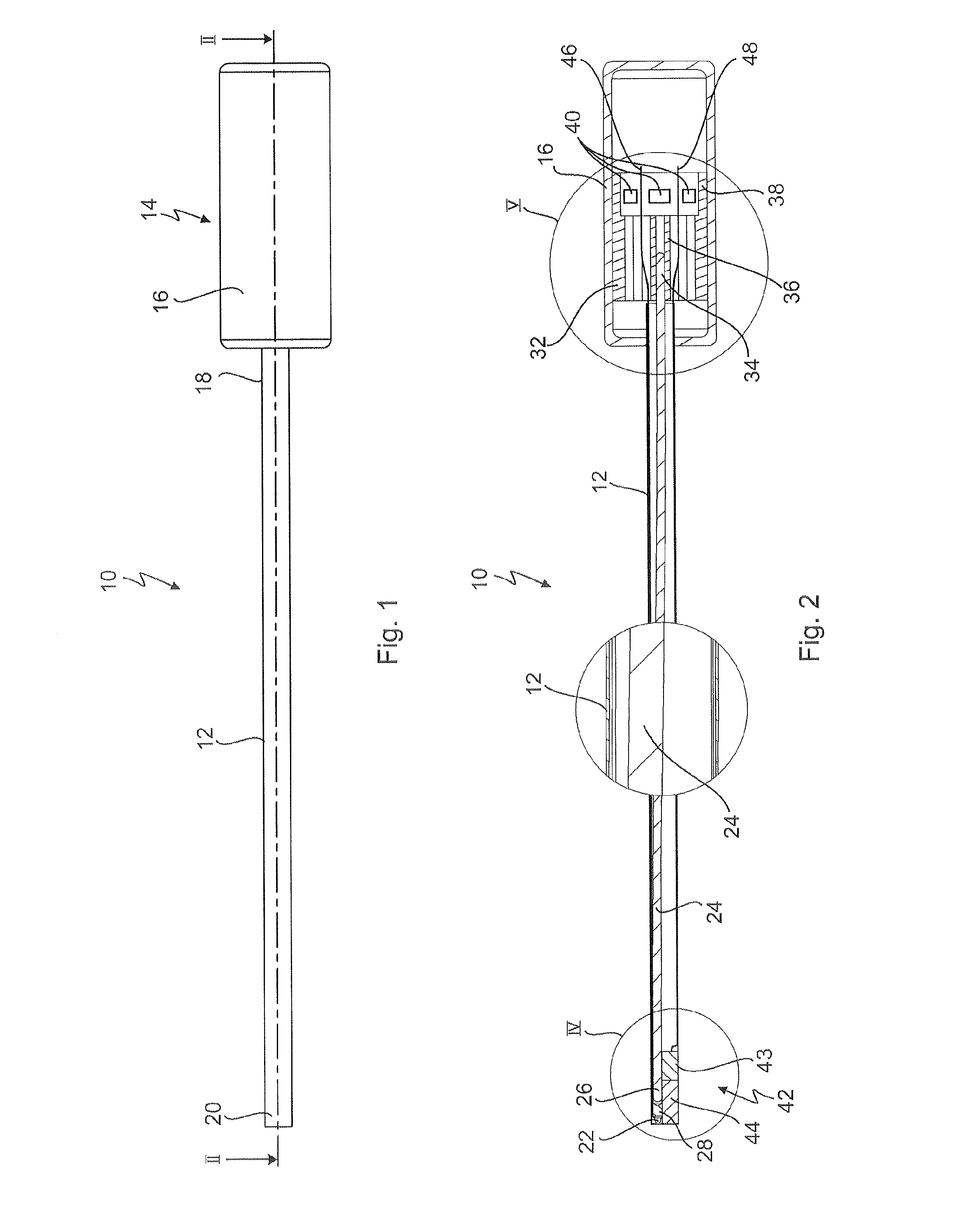
[0069]FIG. 1 shows an endoscope, in particular a medical video endoscope, which is provided with the general reference symbol 10.

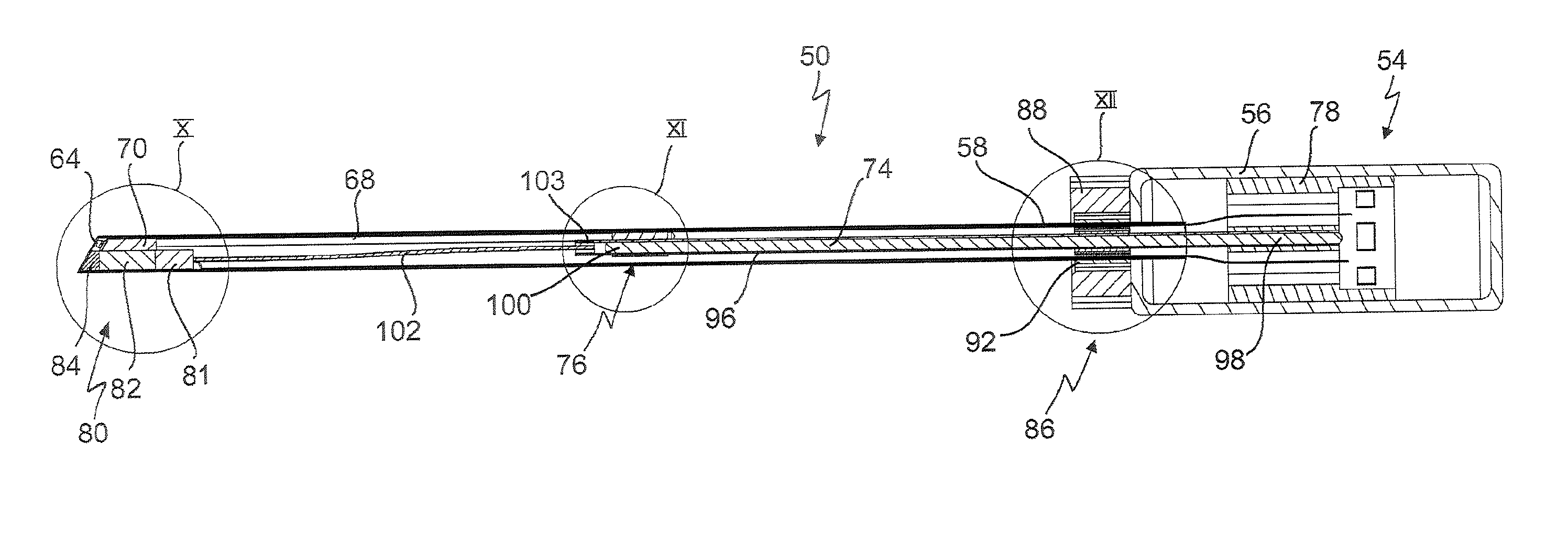
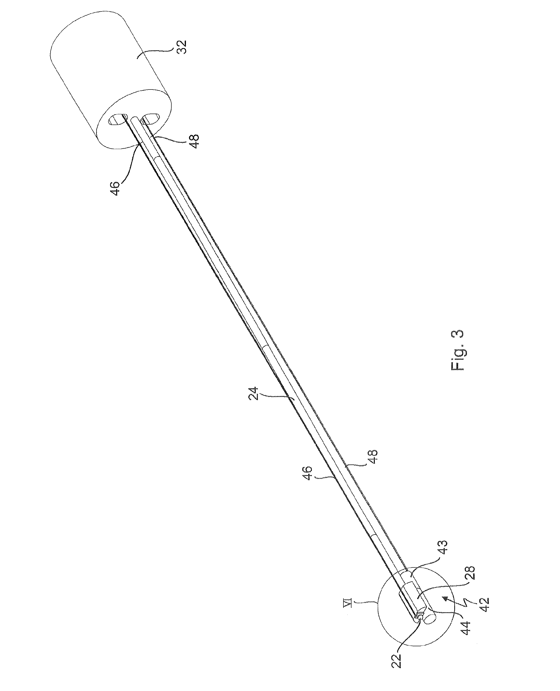
[0070]FIGS. 2 to 6 illustrate further details of the endoscope 10, to which reference will likewise be made in the following text.

[0071]The endoscope 10 generally has an elongated shaft 12 and a headpiece 14 with a housing 16 at a proximal end 18 of the shaft 12. A distal end of the shaft 12 is provided with the reference symbol 20 in FIG. 1.

[0072]A light source 22 is arranged in a distal area of the shaft 12 which is shown on its own in particular in FIGS. 4 and 6, and the light source 22 is preferably in the form of a high-power light-emitting diode (LED or OLED). The light source 22 produces lost heat during operation.

[0073]In order to lead away the lost heat from the light source 22, in order to prevent the shaft 12 from being heated above the maximum permissible temperature of 41° C. in accordance with the medical product law, particularly in the area...


PUM


Abstract

An endoscope comprises an elongated shaft, a headpiece at a proximal end of the shaft, the headpiece having a housing, at least one light source which is arranged in the shaft in a distal area thereof, and produces lost heat, and a passive cooling which has at least one heat pipe which is arranged in the shaft and is thermally coupled to the at least one light source in order to lead away the lost heat in the proximal direction. The at least one heat pipe extends into the headpiece, and a heat sink body is arranged in the headpiece, to which heat sink body the at least one heat pipe is thermally coupled, and which absorbs the lost heat from the at least one heat pipe and emits the lost heat to the environment directly or via the housing of the headpiece.

Description

CROSSREFERENCE TO RELATED APPLICATION[0001]This application claims priority from German patent application 102010024003.6, filed on Jun. 11, 2010. The entire contents of these priority application is incorporated herein by reference.BACKGROUND OF THE INVENTION[0002]The invention relates to an endoscope having at least one light source and a passive cooling in order to lead away lost heat produced by the light source, in proximal direction.[0003]The present invention relates in particular to a medical endoscope, which is used as a viewing instrument during minimal invasive surgery. In the case of a medical endoscope such as this, the elongated shaft is partially inserted into the body through an artificially created or natural opening.[0004]Nowadays, endoscopes have one or more light sources which are integrated in the endoscope shaft and are in the form of light-emitting diodes (LEDs). The integration of one or more light sources in the shaft of the endoscope, normally in the distal...

Claims


Application Information

Patent Timeline
IPC IPC(8): A61B1/04A61B1/06
CPCA61B1/00066A61B1/00121A61B1/0676A61B1/0684F28D2021/005A61B1/128G02B23/2476G02B23/2484F28D15/04A61B1/12
Inventor SCHRADER, STEPHANOGINSKI, STEFANBRUEGGEMANN, DANIEL
Owner KARL STORZ GMBH & CO KG
Learn More