Noise and vibration mitigating mat

a technology of noise and vibration, applied in the direction of resiliently mounted floors, temporary pavings, flooring, etc., can solve the problems of unwanted noise and vibration pollution, truck passing over a road, and generating impact noise on horizontal surfaces such as floors or road surfaces, and achieve the effect of effectively absorbing nois

Inactive Publication Date: 2011-12-22
PLITEQ INC
View PDF5 Cites 33 Cited by
  • Summary
  • Abstract
  • Description
  • Claims
  • Application Information

AI Technical Summary

Benefits of technology

[0010]The noise and vibration mitigating map effectively absorbs noise and vibration inhibiting noise and vibration from propagating to surrounding structure. When used in certain environments, the contoured bottom surface also provides for effective drainage.

Problems solved by technology

In many situations, noise is generated on horizontal surfaces such as floors or road surfaces due to various impacts.
This noise often propagates into surrounding structures creating undesirable noise and vibration pollution.
For example, a truck passing over a road generates impact noise.
Such impact noise typically travels through the road and then to adjacent structures.
Likewise, machinery, which vibrates during use, often results in impact and / or vibrational noise passing through the floor and into adjacent structures.
Similarly, locomotives and railcars passing over tracks generate impact and vibrational noise, which passes into the ground and potentially into adjacent structures such as homes, roads or bridges.
Mitigating impact and vibrational noise generated by locomotives and railcars is especially problematic due to the relatively large axle loads of locomotives and railcars on the tracks.
As mentioned above, impact noise and vibrations generated under the above and similar conditions is undesirable due to the noise and vibration pollution created in adjacent and surrounding structures.

Method used


Image

  • Noise and vibration mitigating mat
  • Noise and vibration mitigating mat
  • Noise and vibration mitigating mat

Examples


Embodiment Construction

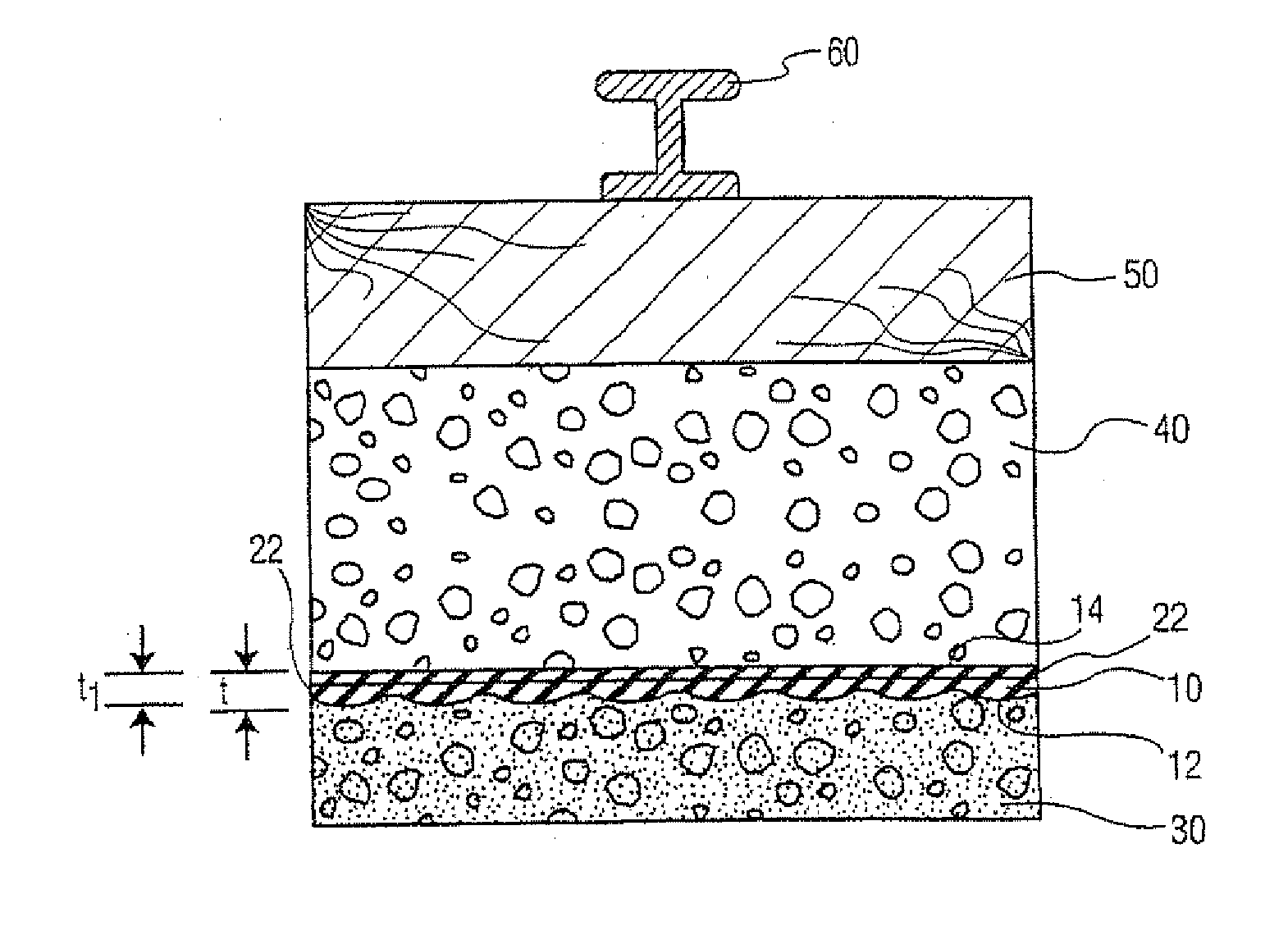
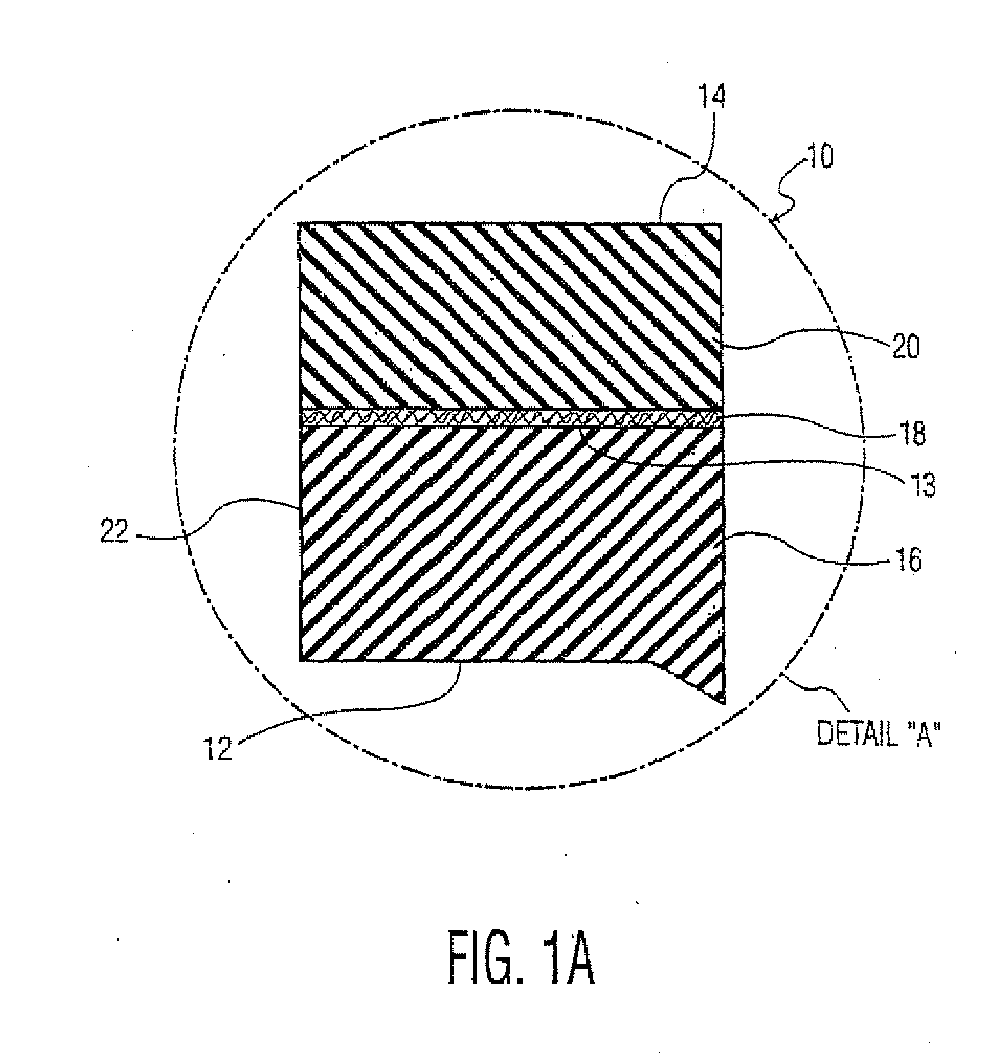
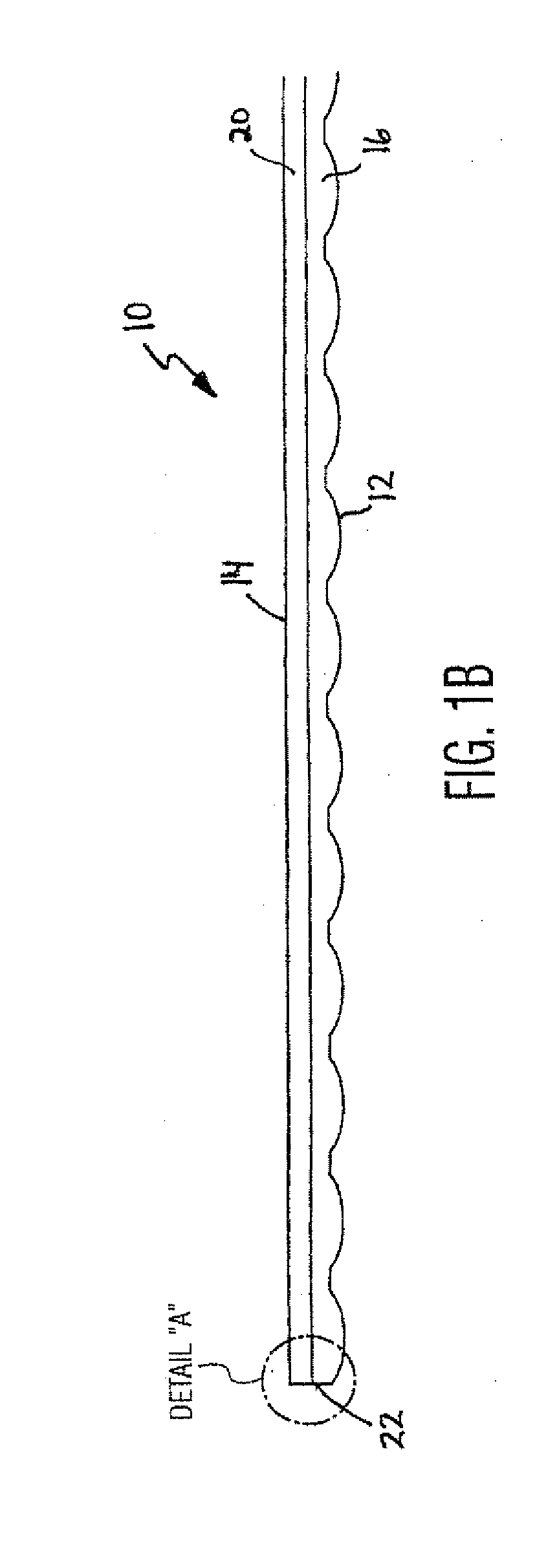
[0017]Turning now to FIGS. 1A and 1B, a noise and vibration mitigating mat is shown and is generally identified by reference numeral 10. As can be seen, mat 10 has a bottom surface 12, a top surface 14 and sides 22 extending between the surface 12 and 14. The mat 10 can be produced in a continuous roll such that the surfaces 12 and 14 extend for a distance between the sides 22. The top surface 14 and the oppositely facing bottom surface 12 are generally parallel to each other and are spaced apart by an overall thickness. The bottom surface 12 is contoured such that the thickness varies between a minimum thickness t1 measured at the minimum dimension of the contour and a maximum thickness t measured at the maximum dimension of the contour. As the mat 10 is manufactured in continuous sheets, the length of the mat 10 is governed by the particular installation. This provides flexibility during installation, and other advantages which will be more fully described below.

[0018]In this embo...


PUM

PropertyMeasurementUnit
vibration energyaaaaaaaaaa
energyaaaaaaaaaa
sound absorptionaaaaaaaaaa

Abstract

A noise and vibration mitigating mat having top and bottom surfaces comprises a first layer formed of recycled bound rubber product, the first layer having a contoured bottom surface and a generally flat top surface, a second layer on the top surface of the first layer, the second layer being formed of a fabric and a third layer on the second layer and being formed of recycled rubber product.

Description

CROSS-REFERENCE TO RELATED APPLICATIONS[0001]This application is a continuation-in-part of International PCT Application No. PCT / US2003 / 031348 filed on Oct. 1, 2003 and published under No. WO 2004 / 031501 on Apr. 15, 2004, designating the United States, which claims the benefit of U.S. Provisional Patent Application No. 60 / 415,054 filed on Oct. 1, 2002.FIELD OF THE INVENTION[0002]The present invention relates generally to sound absorption, and more particularly to a noise and vibration mitigating mat for mitigating impact generated and structure borne noise.BACKGROUND OF THE INVENTION[0003]In many situations, noise is generated on horizontal surfaces such as floors or road surfaces due to various impacts. This noise often propagates into surrounding structures creating undesirable noise and vibration pollution. For example, a truck passing over a road generates impact noise. Such impact noise typically travels through the road and then to adjacent structures. Likewise, machinery, whi...

Claims


Application Information

Patent Timeline
Patent Type & Authority Applications(United States)
IPC IPC(8): E04B1/98E04B5/43E04C2/22E04B1/84E04F15/22E04C2/20B32B3/30B32B7/03B32B25/10E01B19/00E01C3/06F16F1/373G10K11/168
CPCB32B3/30B32B25/10E01B2/00G10K11/168E01C3/06F16F1/3737F16F15/08E01B19/003B32B7/03B32B2471/04B32B2317/22B32B2272/00B32B2307/72B32B2307/56B32B2375/00B32B2270/00B32B2250/03B32B2319/00
Inventor DOWNEY, PAUL C.
Owner PLITEQ INC
Why Eureka
Try Eureka