Laminated bus bar

a technology bus bars, which is applied in the direction of laminated bus bars, power conversion systems, electric cable installations, etc., can solve the problems of difficult laminated bus bars b>3/b>,

Active Publication Date: 2011-12-22
FUJI ELECTRIC CO LTD
View PDF4 Cites 30 Cited by
  • Summary
  • Abstract
  • Description
  • Claims
  • Application Information

AI Technical Summary

Benefits of technology

[0023]According to the structure described above, the creepage distance between the connection terminal sections separated from each other along the edges of the insulator plates and led out in perpendicular to the edges of the insulator plates is elongated for the groove of creepage formed additionally as compared with the creepage distance in the conventional structure, in which the insulator plate edge is linear. By setting the width of the groove of creepage to be equal to or more than 2.5 mm wide, the creepage distance that follows the International Standard IEC60077-1 is obtained and the insulation performances of the laminated bus bar are improved. Therefore, the laminated bus bar according to the invention is applicable to the electric power converters for the rolling stock.

Problems solved by technology

Therefore, it is difficult for laminated bus bar 3 having the conventional structure to secure high insulation performances.
If the inverter unit is applied to the electric power converters on the rolling stock, it will be difficult for laminated bus bar 3 having the conventional structure to follow the International Standard IEC60077-1 due to the shortage of the creepage distance between the connection terminal sections.

Method used


Image

  • Laminated bus bar
  • Laminated bus bar
  • Laminated bus bar

Examples


Embodiment Construction

[0034]Now the invention will be described in detail below with reference to the accompanied drawings which illustrate the preferred embodiments of the invention. In the following descriptions and the drawings which illustrate the preferred embodiments, the same reference numerals as used in FIGS. 5 through 7 are used to designate the same constituent elements and their duplicated descriptions are not made for the sake of simplicity.

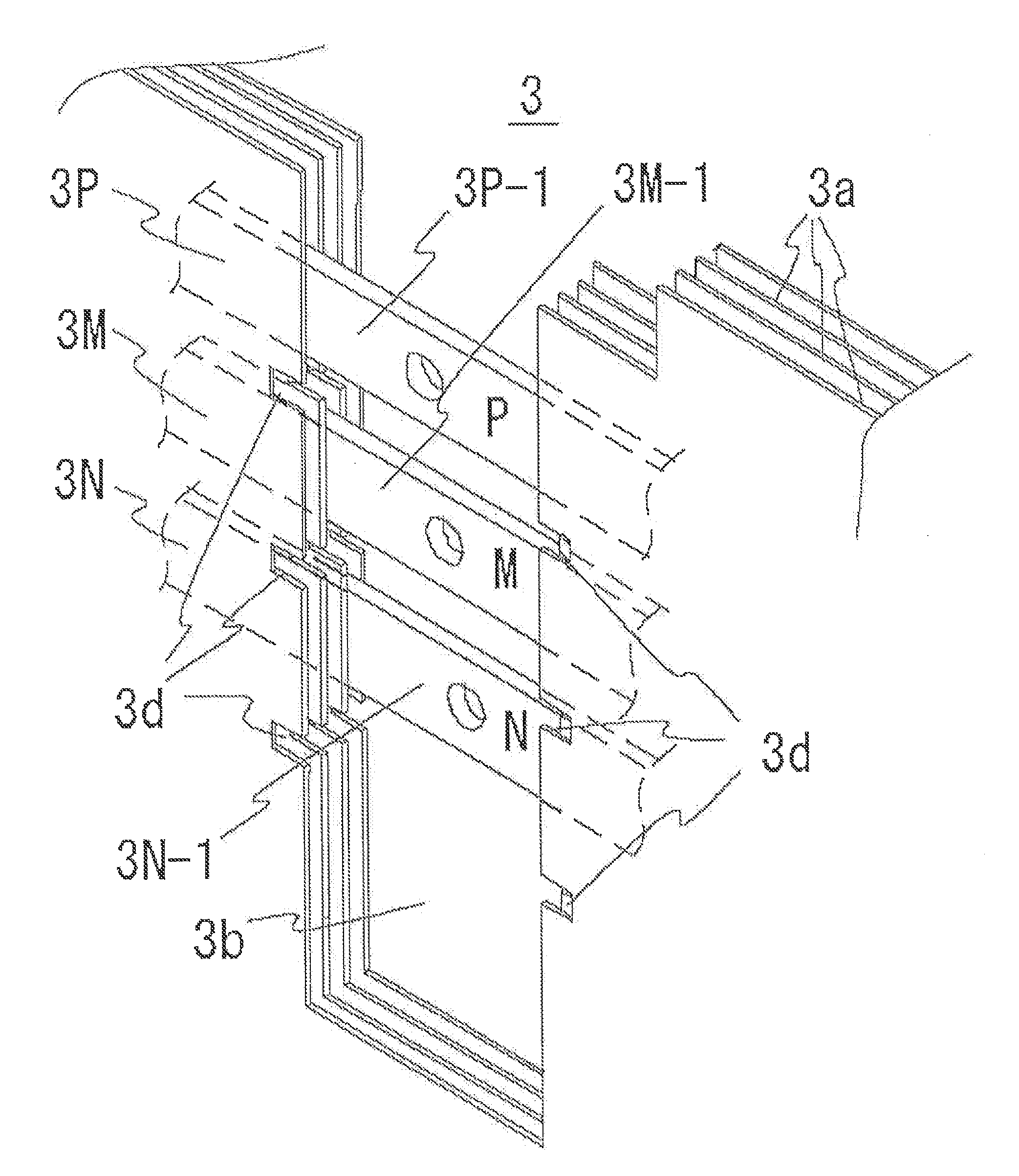
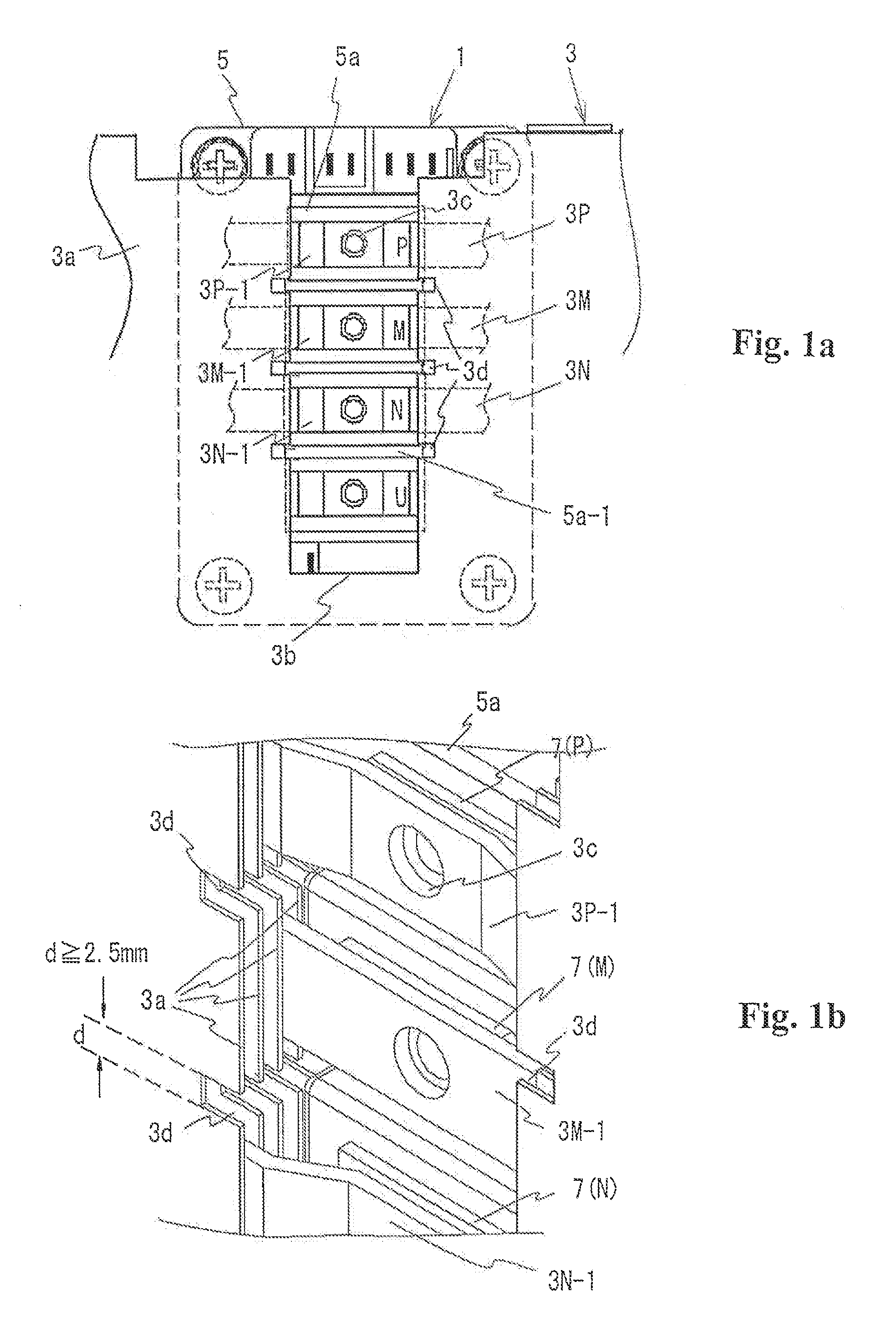
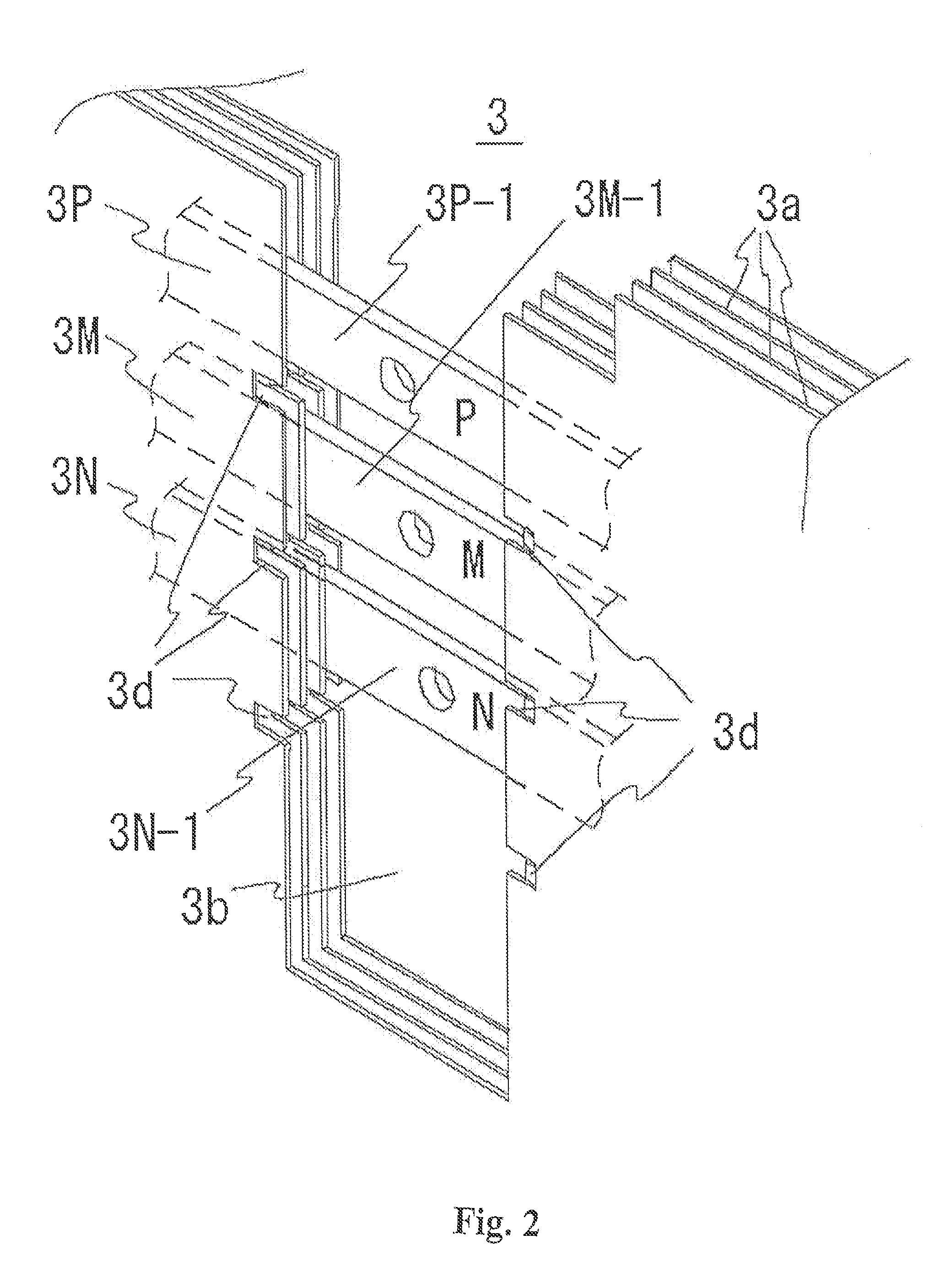
[0035]Laminated bus bar 3 according to the invention is fundamentally the same with the conventional laminated bus bar. Laminated bus bar 3 according to the invention is different from the conventional laminated bus bar in that grooves of creepage (hereinafter referred to as “creepage grooves”) 3d are formed on the edges of insulator plates 3a corresponding to connection terminal sections 3P-1, 3M-1, and 3N-1. Connection terminal sections 3P-1, 3M-1, and 3N-1 are led out in parallel to each other into terminal-leading-out-window 3b of insulator plates 3a....


PUM


Abstract

A laminated bus bar is applied to a main wiring circuit of an electric power converter and connected to a semiconductor module. The laminated bus bar includes insulator plates laminated together, and conductors interposed between the insulator plates. Each conductor includes a connection terminal section led out in accordance with an arrangement of a main circuit terminal on the semiconductor module. A creepage groove is formed on an edge of each of the insulator plates in accordance with a position between the connection terminal sections. The laminated bus bar facilitates elongation of the creepage distance between the connection terminals.

Description

FIELD OF THE INVENTION[0001]The present invention relates to laminated bus bars applied to a main wiring circuit in electric power converters and such apparatuses for connecting the main wiring circuit to a semiconductor module. Specifically, the invention relates to the insulation structure between the connection terminals of the laminated bus bar.BACKGROUND[0002]Recently, laminated bus bars have been employed very often in the electric power converters for the conductor in a main wiring circuit between a semiconductor module constituting an inverter section and a power supply for reducing the wiring inductance of the main wiring circuit. The laminated bus bar has a laminate structure formed by laminating conductors for the wiring circuit and insulator plates alternately into a sandwich-shaped unit (Patent Document 1).[0003]As for the semiconductor module in the inverter section described above, the applicant of the present invention has proposed a four-in-one-type three-level IGBT...

Claims


Application Information

Patent Timeline
Patent Type & Authority Applications(United States)
IPC IPC(8): H02G5/00
CPCH02M7/003H02M7/487H02G5/005H05K7/14329
Inventor TAKAHASHI, KIYOSHI
Owner FUJI ELECTRIC CO LTD
Why Eureka
Try Eureka