

Tube coupling
a technology of coupling and tube, which is applied in the direction of hose connection, sleeve/socket joint, pipe-joint, etc., can solve the problems of inability to insert the collet into the housing, and the assembly with the tube support incorrectly aligned, so as to facilitate the alignment of the collet, improve the release of the tube, and increase the effect of productivity
- Summary
- Abstract
- Description
- Claims
- Application Information
AI Technical Summary
Benefits of technology
Problems solved by technology
Method used
Image

Examples
Embodiment Construction
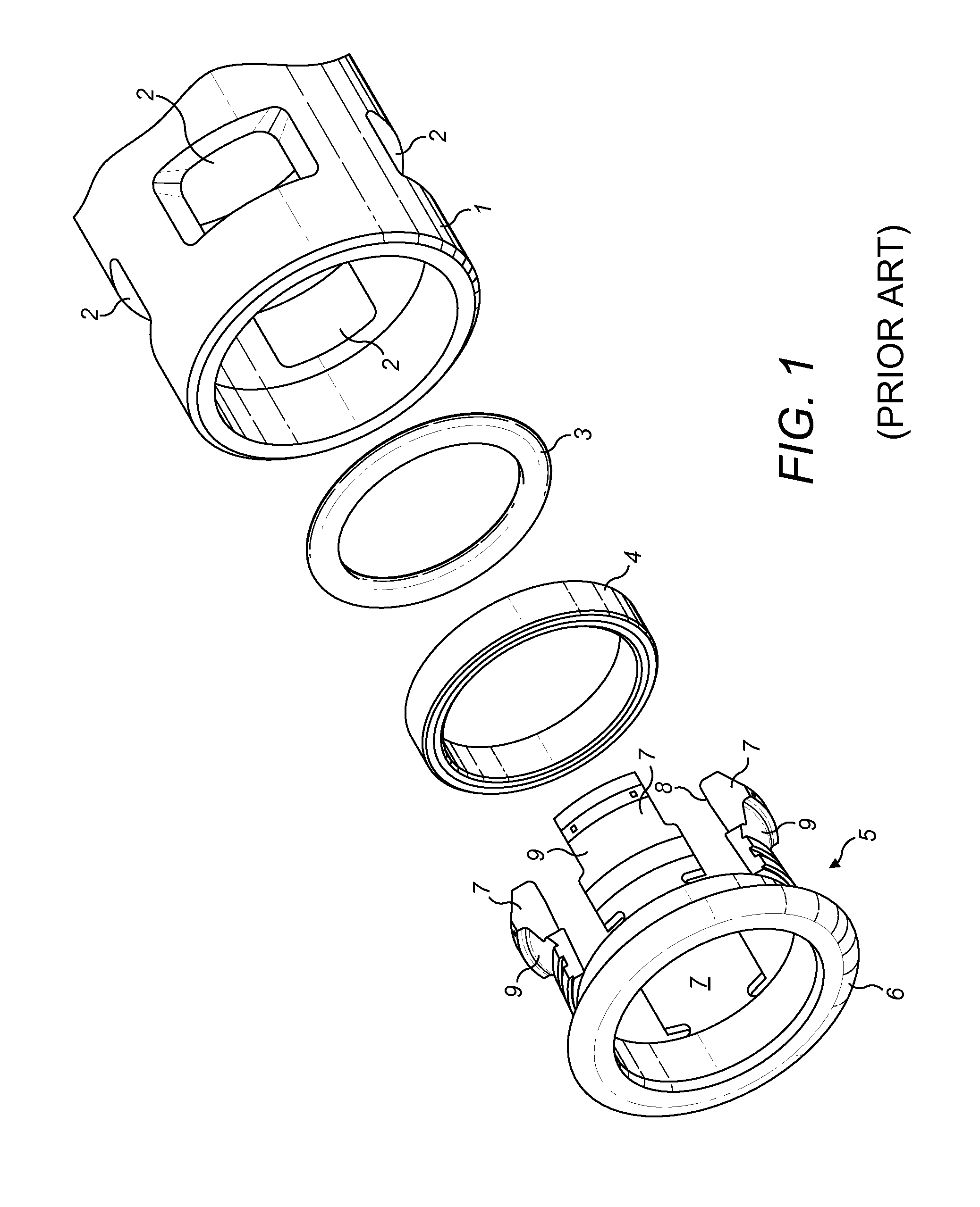
[0027]The coupling is, in most respects, similar to the coupling described in FIG. 1 above and the description of this will not be duplicated here.
[0028]The same components have been represented with the same reference numerals where appropriate.
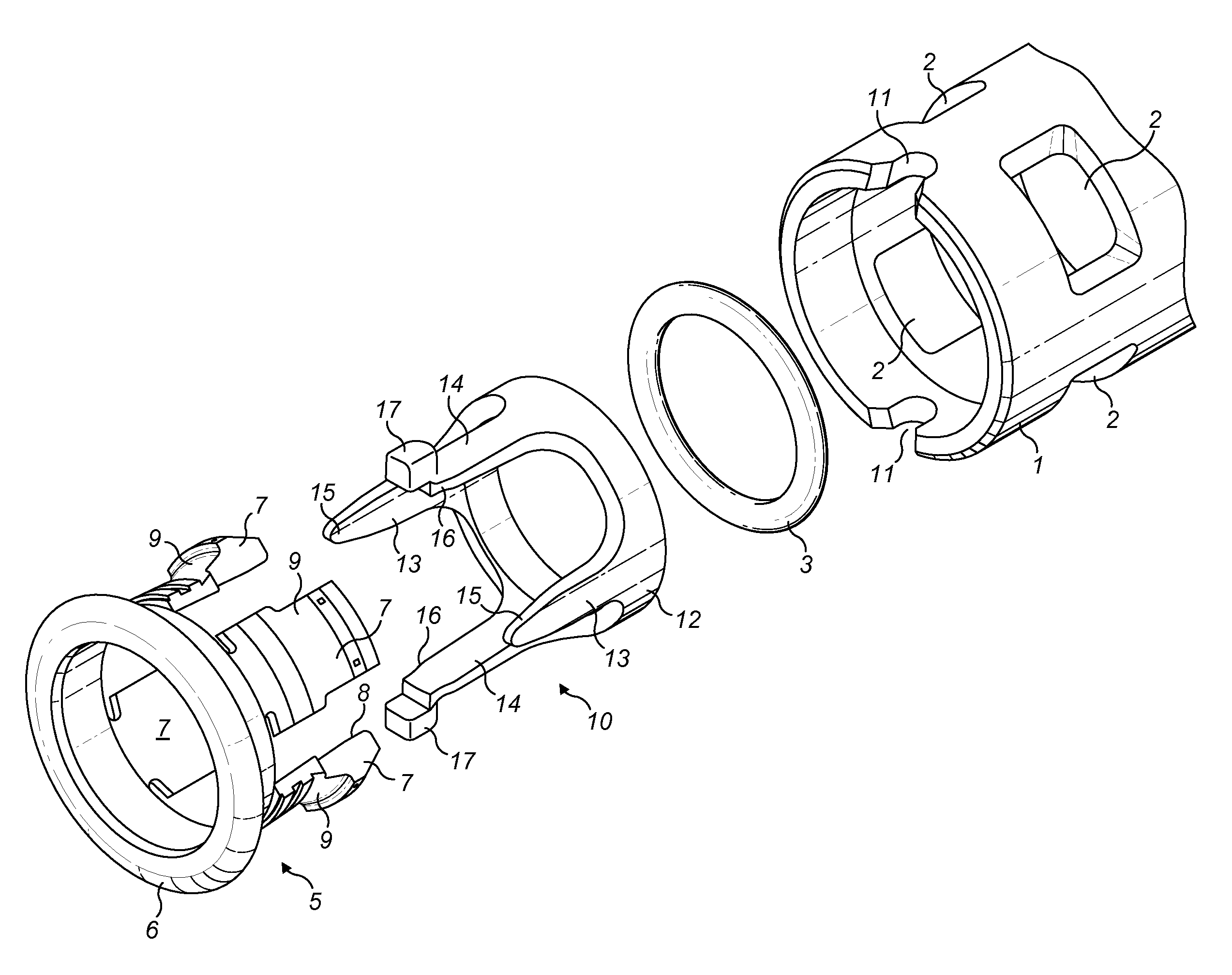
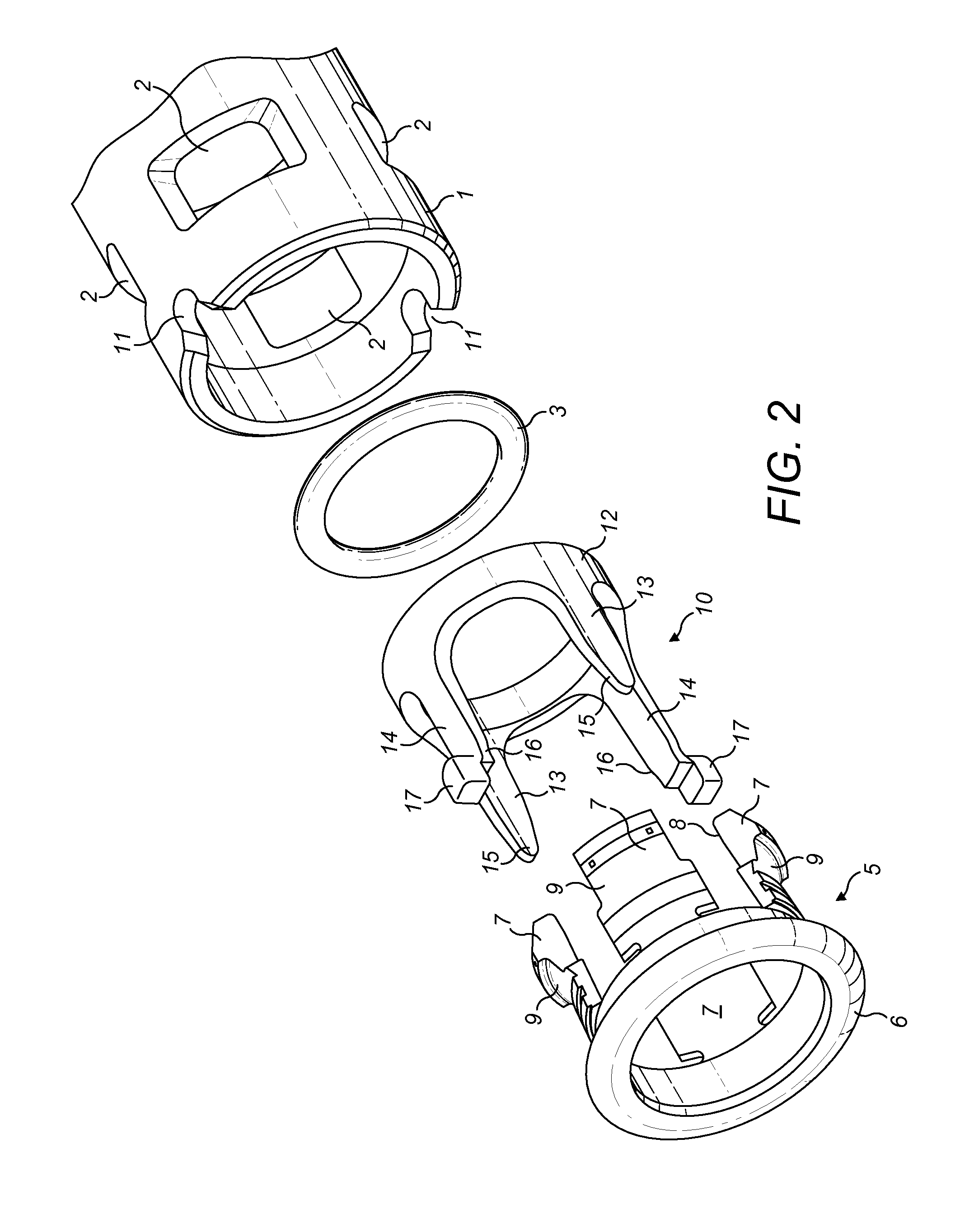
[0029]The main difference is that the spacer washer of FIG. 1 has now been replaced by a tube support 10 which will be described in greater detail below. The other difference is that a pair of notches 11 have been formed on the proximal face of the body 1 for reasons which will be described below.
[0030]The tube support 10 comprises a tube support ring 12 at the distal end. This may be a complete or a split ring. Projecting distally from the tube support ring 12 are a pair of first castellations 13 and a pair of second castellations 14 and it should be noted that the number and positioning of each type of castellation may be varied. The first pair of castellations are simple straight projections which have a taper 15 such that their circumfer...
PUM
 Abstract
Description
Claims
Application Information