Driving circuit for LED lamp

a technology of led lamps and driving circuits, which is applied in the direction of electric variable regulation, process and machine control, instruments, etc., can solve the problems of waste of design costs, specific-purpose pwm controllers are certainly expensive, and the driving circuit using specific-purpose pwm controllers is also expensive. achieve the effect of reducing design costs

Inactive Publication Date: 2011-12-22
TPV ELECTRONICS (FUJIAN) CO LTD
View PDF4 Cites 50 Cited by
  • Summary
  • Abstract
  • Description
  • Claims
  • Application Information

AI Technical Summary

Benefits of technology

[0010]The invention introduces the driving circuit to directly supply power to the LED lamp including fewer strings each through which more current flows without using a specific-purpose PWM controller IC so as to reduce design cost and avoid the EMI problem caused by the switching of the power transistor(s) of the DC to DC boost converter. Moreover, the invention introduces the constant current circuits to control the currents flowing through the strings to be constant when working and accordingly uses the PWM dimming. Furthermore, the overvoltage protection circuit to perform the overvoltage protection when a voltage at one input terminal is too high or a short circuit occurs in one string.

Problems solved by technology

The specific-purpose PWM controller IC is certainly expensive and hence the driving circuit using the specific-purpose PWM controller IC is also expensive.
If the LED lamp in the LCD panel (model name “LM215WF4”) is driven by the PWM controller IC (model name “TA9690GN”), it will waste design cost.

Method used


Image

  • Driving circuit for LED lamp
  • Driving circuit for LED lamp
  • Driving circuit for LED lamp

Examples


Embodiment Construction

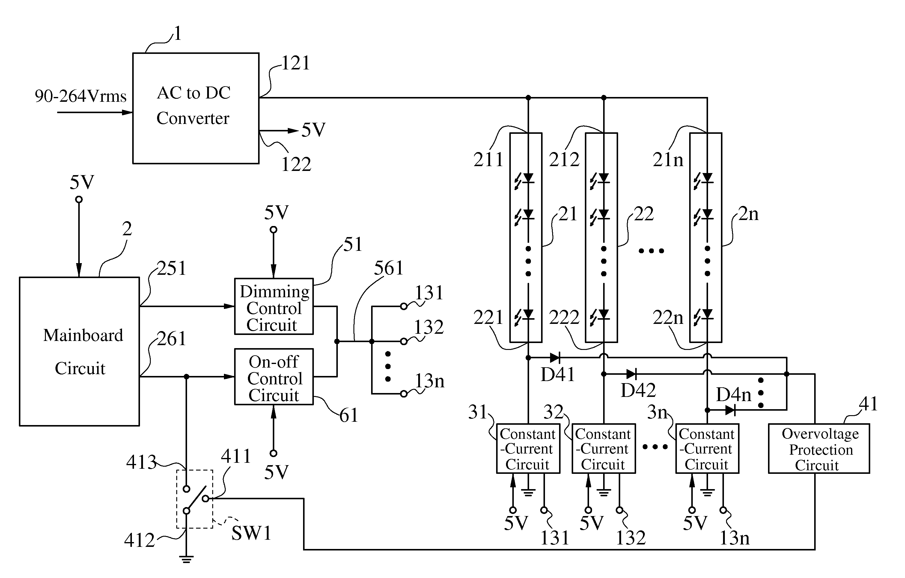
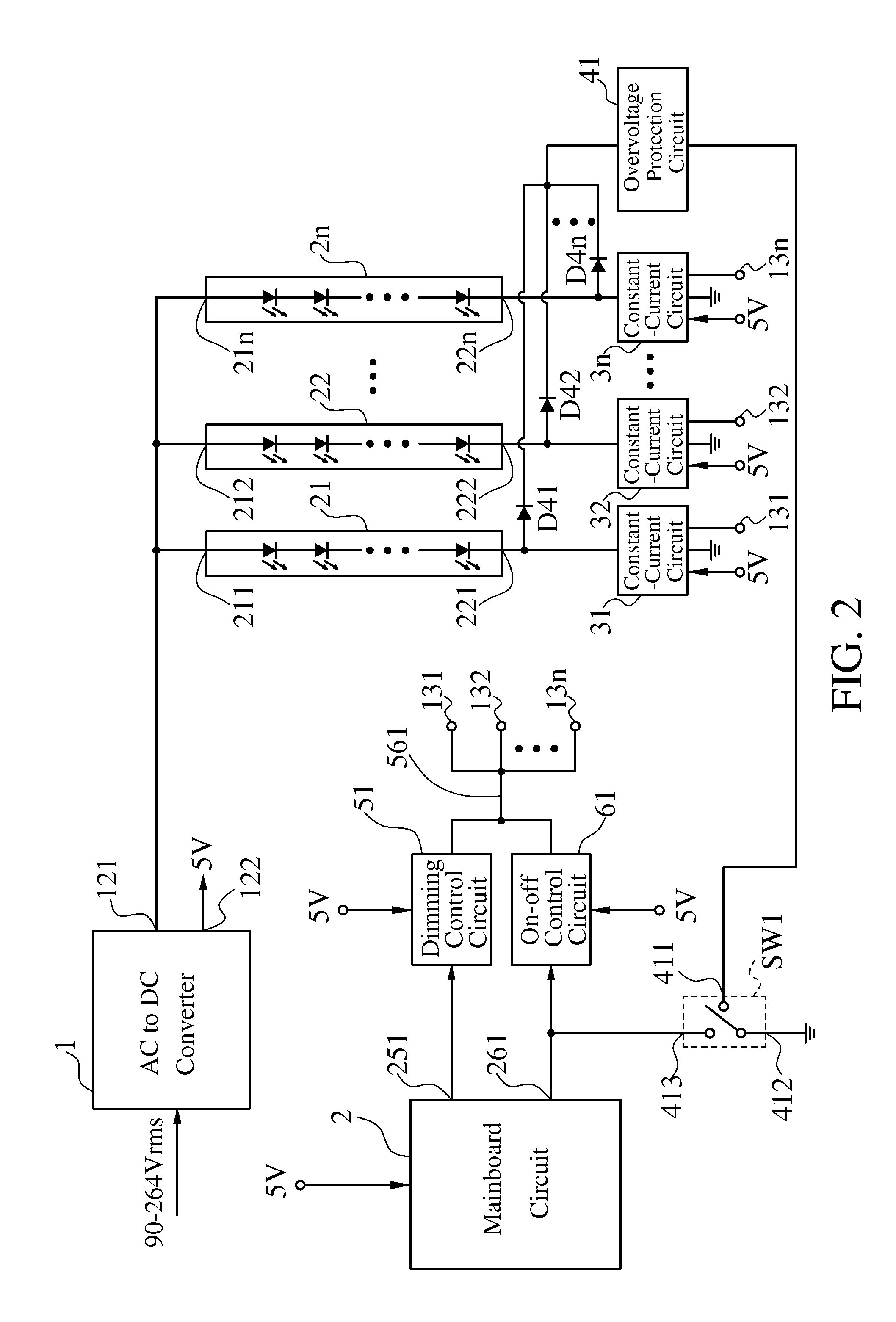
[0019]FIG. 2 is a schematic diagram illustrating an embodiment of a driving circuit for an LED lamp according to the present invention. Referring to

[0020]FIG. 2, An LED lamp includes no more than 4 strings 21-2n, where n is a positive integer. Each string 2i has an input terminal 21i and an output terminal 22i and includes a plurality of LEDs coupled in series between the input terminal 21i and the output terminal 22i, where i is any integer from 1 to n. A driving circuit for the LED lamp includes an AC to DC converter 1, a plurality of constant current circuits 31-3n, a plurality of diodes D41-D4n, an overvoltage protection circuit 41, a dimming control circuit 51, an on-off control circuit 61 and a switch SW1.

[0021]An AC voltage of 90-264 Vrms input to the AC to DC converter 1. The AC to DC converter 1 converts the AC voltage into two DC voltages. A DC voltage of no more than 70V outputted from a terminal 121 to the input terminals 211-21n of the strings 21-2n. The DC voltage slig...


PUM


Abstract

A driving circuit for an LED lamp including no more than 4 strings each having an input and an output terminals outputs a DC voltage of no more than 70V to the input terminals. The driving circuit includes constant current circuits each coupled between the output terminal of a corresponding string and ground. An on-off control signal controls whether the constant current circuits work to control whether the LED lamp works. A dimming control signal controls a duty cycle of working of to the constant current circuits to control a brightness of the LED lamp. The driving circuit further includes an overvoltage protection circuit and a switch. When a voltage at one input terminal is too high or a short circuit occurs in one string, the overvoltage protection circuit outputs an overvoltage control signal and accordingly the switch forces the on-off control signal to control the constant current circuits not to work.

Description

BACKGROUND OF THE INVENTION[0001]1. Field of the Invention[0002]The present invention relates to a driving circuit for a light-emitting diode (LED) lamp. More particularly, the present invention relates to a driving circuit for an LED lamp including fewer strings each through which more current flows.[0003]2. Description of the Related Art[0004]A liquid crystal display (LCD) such as LCD monitor gradually uses an LED lamp as a backlight source. The LED lamp includes plenty of LEDs and hence the LEDs are coupled in series and / or parallel. A driving circuit for the LED lamp usually uses a direct-current (DC) to DC boost is converter so that a specific-purpose integrated circuit (IC) is required to control the DC to DC boost converter.[0005]FIG. 1 is a schematic diagram illustrating a conventional driving circuit for an LED lamp. Referring to FIG. 1, an LED lamp includes a plurality of strings 21-2n and each string 2i has an input terminal 21i and an output terminal 22i, where n is a po...

Claims


Application Information

Patent Timeline
Patent Type & Authority Applications(United States)
IPC IPC(8): H05B37/03
CPCY02B20/341H05B33/0827H05B45/46H05B45/382Y02B20/30
Inventor YU, ZUO-SHANGLEE, TSUNG-YENFENG, JIE
Owner TPV ELECTRONICS (FUJIAN) CO LTD
Why Eureka
Try Eureka