Composite casing structure

a casing structure and composite technology, applied in the direction of casings/cabinets/drawers, instruments, portable computer details, etc., can solve the problems of complex and time-consuming entire fabrication process, failure to meet the requirements of chassis manufacturers for rapid and mass production, etc., to reduce the overall weight and fabrication cost, and increase processing speed

Inactive Publication Date: 2011-12-22
GETAC TECH CORP
View PDF4 Cites 39 Cited by
  • Summary
  • Abstract
  • Description
  • Claims
  • Application Information

AI Technical Summary

Benefits of technology

[0014]The above structural design with a combination of the metal plate and the plastic frame has not only a thin housing (the metal plate) but also a secure and lightweight backbone (the plastic frame). Moreover, complex structures are designed on the plastic frame, and high-rigidity struc

Problems solved by technology

In the prior art, since complex structures (for example, studs) are fixed on the surface of the AlMg chassis by laser welding or adhesion with an anaerobic adhe

Method used


Image

  • Composite casing structure
  • Composite casing structure
  • Composite casing structure

Examples


Embodiment Construction

[0024]A composite casing structure of an electronic device according to the present invention is illustrated by taking an application to a chassis (i.e., Part A) of a notebook computer for industrial or military purposes. Definitely, the products applying the present invention and the application range of the present invention are not limited by the following embodiment.

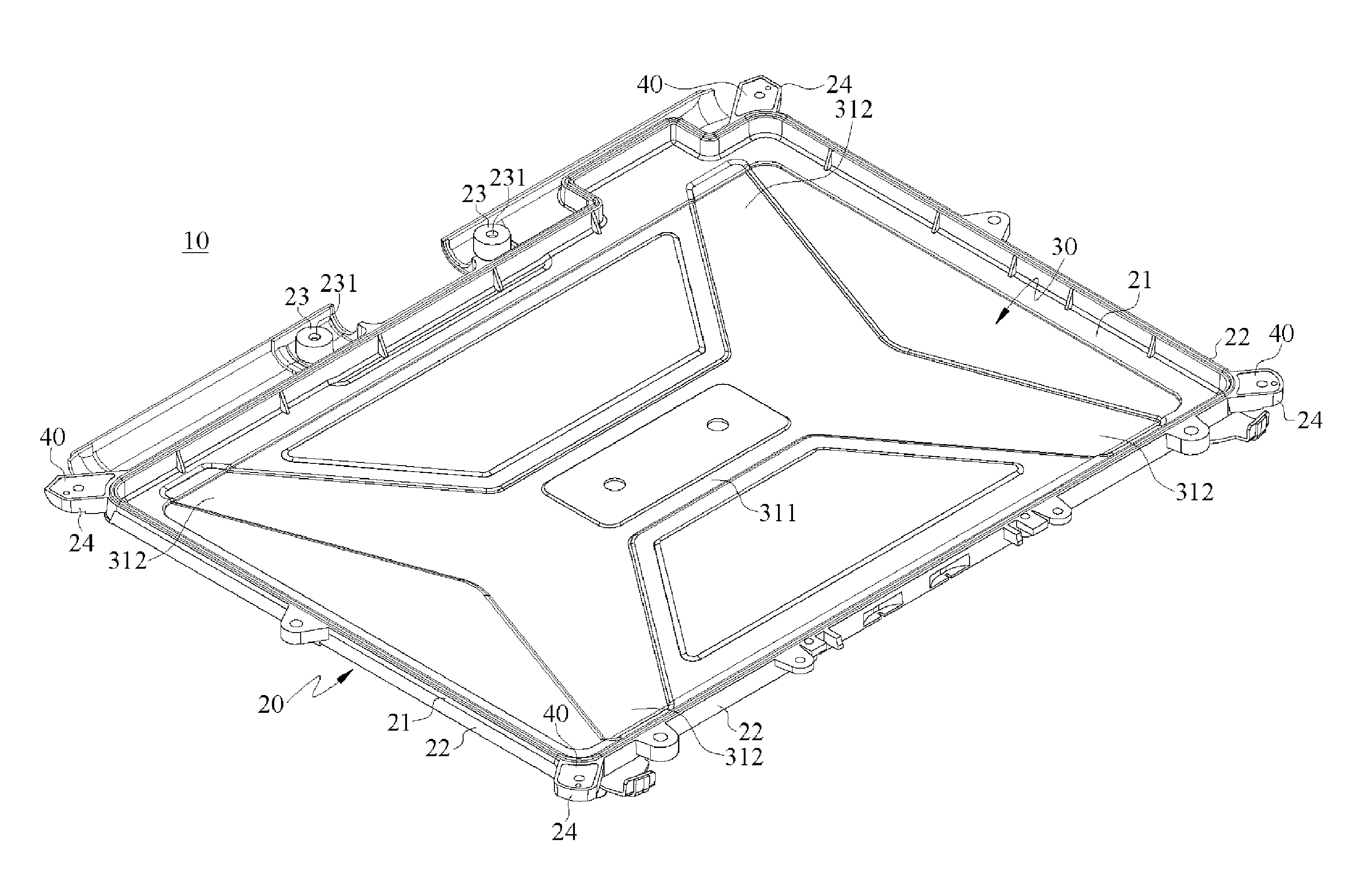
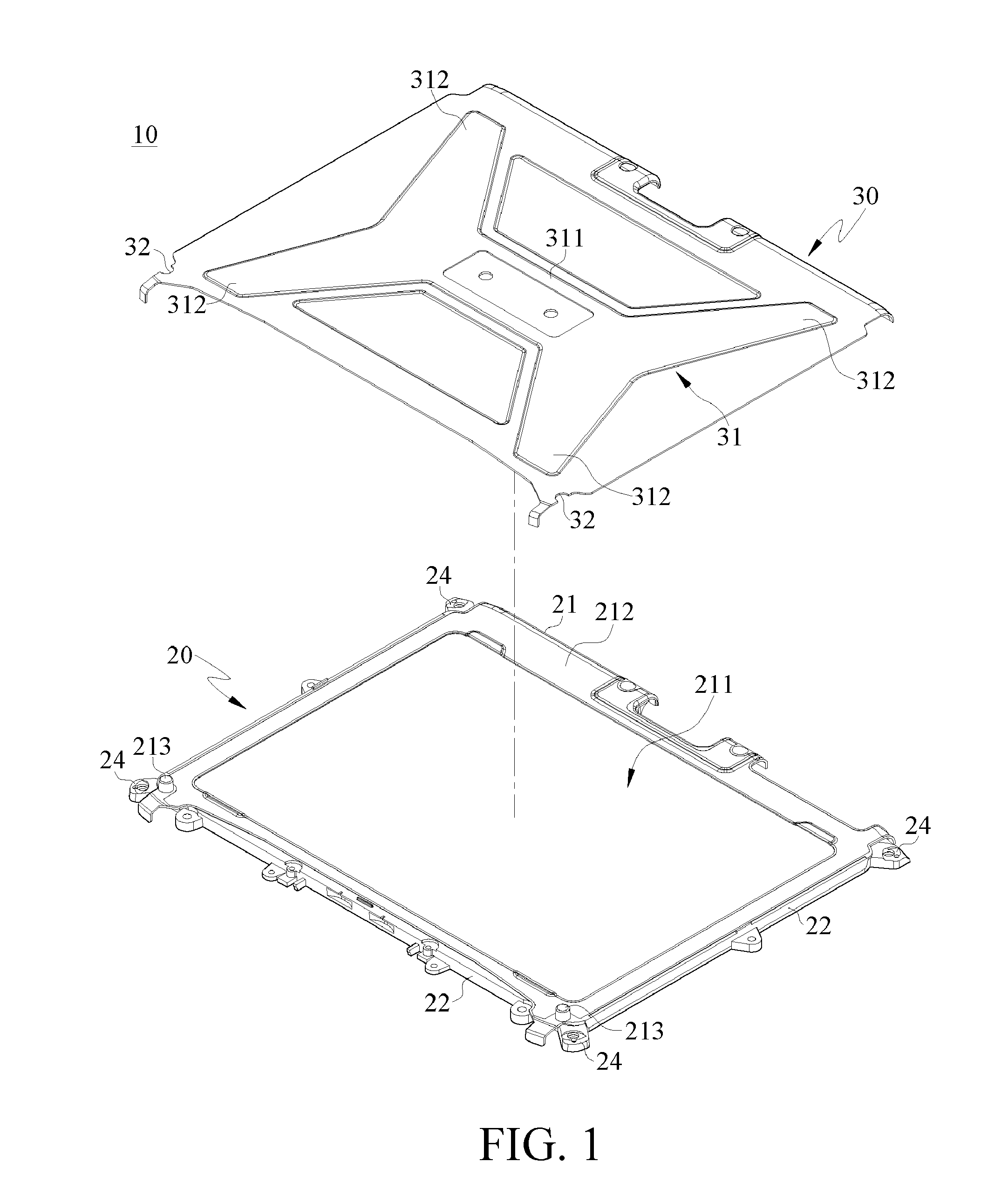
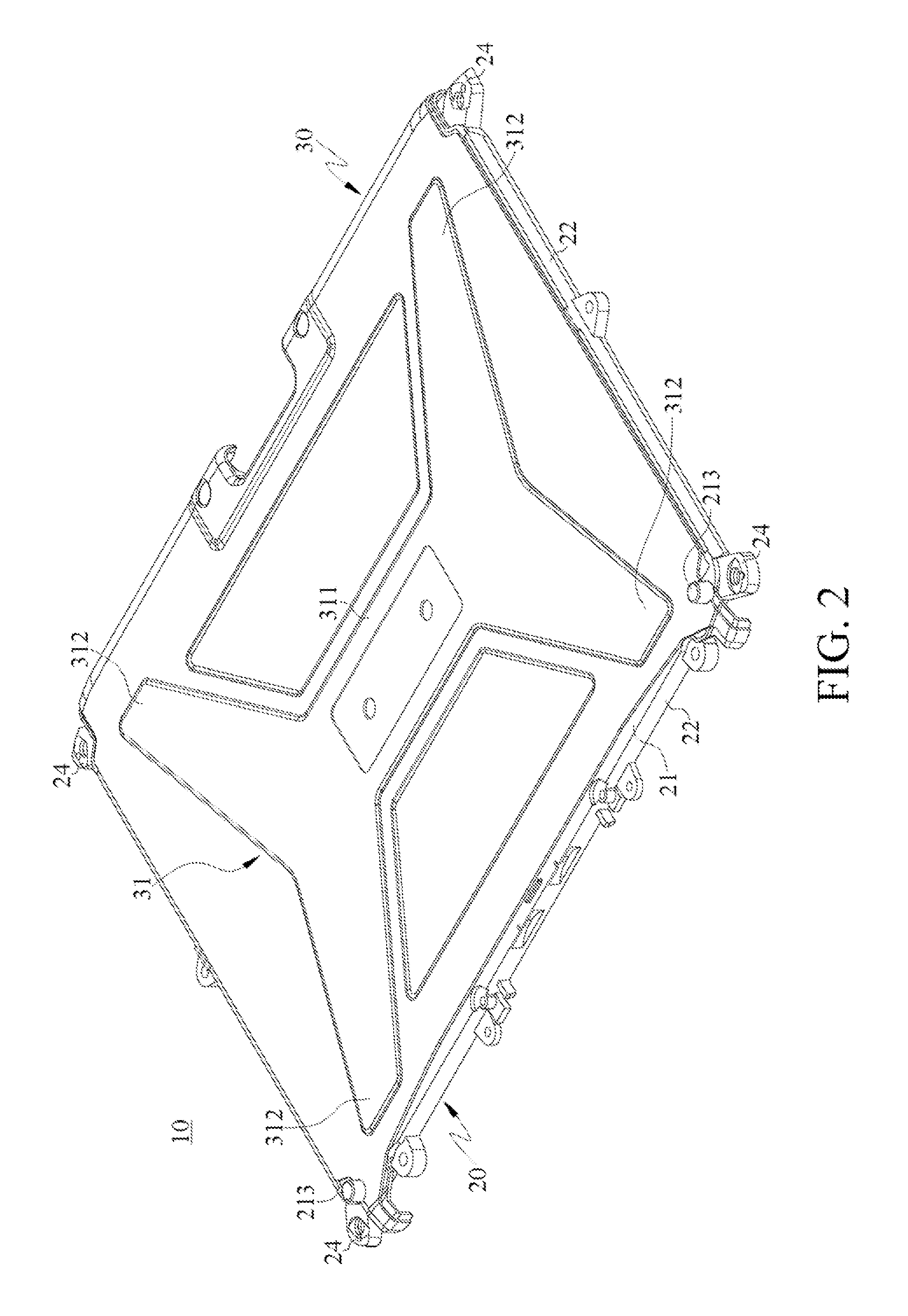
[0025]FIG. 1 is a schematic exploded view of a composite casing structure according to the present invention. FIG. 2 is a schematic outside view of the composite casing structure according to the present invention. FIG. 3 is a schematic enlarged exploded view of the composite casing structure according to the present invention. FIG. 4 is a schematic enlarged outside view of the composite casing structure according to the present invention. FIG. 5 is a schematic enlarged cross-sectional view of the composite casing structure according to the present invention.

[0026]As shown in FIGS. 1 to 5, the composite casing 10 com...


PUM


Abstract

A composite casing structure is applied to a housing of an electronic device. The composite casing structure includes a plastic frame and a metal plate. The plastic frame has a plurality of side walls surrounding four side edges thereof, and at least one open portion is formed by the side walls. The metal plate is combined with the plastic frame, and at least one reinforcing rib is formed on a surface of the metal plate, such that a position of the reinforcing rib is corresponding to a position of the open portion. With such a structural design, the composite casing has a lightweight and high-strength structure.

Description

BACKGROUND OF THE INVENTION[0001]1. Field of the Invention[0002]The present invention relates to a composite casing structure, and more particularly to a composite casing structure applied to a housing of an electronic device.[0003]2. Related Art[0004]A chassis of an ordinary notebook computer is usually divided into four parts. The first part refers to an outer cover of a liquid crystal display (LCD) (LCD Rear Cabinet, commonly referred to as Part A in the industry); the second part refers to a frame of the LCD (LCD Front Cabinet, commonly referred to as Part B in the industry); the third part refers to a keyboard frame (Top Cabinet, commonly referred to as Part C in the industry); and the fourth part refers to a base of the notebook computer (Bottom Cabinet, commonly referred to as Part D in the industry).[0005]In addition, notebook computers are divided into two usage types, that is, commercial notebook computers, and notebook computers for industrial or military purposes. Theref...

Claims


Application Information

Patent Timeline
IPC IPC(8): H05K7/14
CPCG06F1/1656G06F1/1616
Inventor HSIAO, HSIU MIN
Owner GETAC TECH CORP
Why Eureka
Try Eureka