Cascaded condenser for multi-unit geothermal orc

a geothermal orc and condenser technology, applied in the field of vapor expansion systems, can solve the problem of proportional parametric power cost of this process

Inactive Publication Date: 2011-12-29
UNITED TECH CORP
View PDF3 Cites 57 Cited by
  • Summary
  • Abstract
  • Description
  • Claims
  • Application Information

AI Technical Summary

Problems solved by technology

The parasitic power cost of this process is proportional to the amount of fluid used and the relat

Method used


Image

  • Cascaded condenser for multi-unit geothermal orc
  • Cascaded condenser for multi-unit geothermal orc
  • Cascaded condenser for multi-unit geothermal orc

Examples


Embodiment Construction

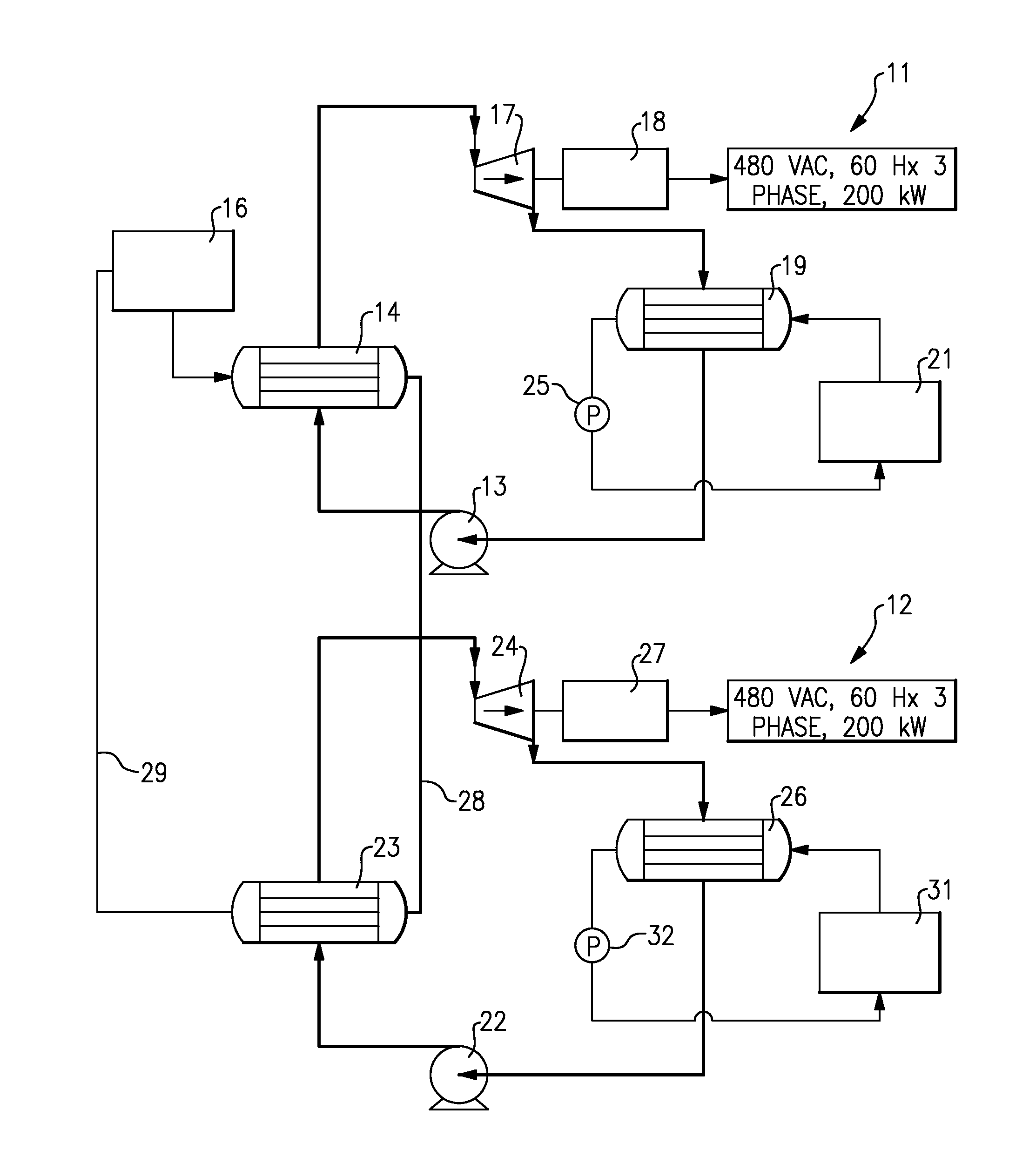
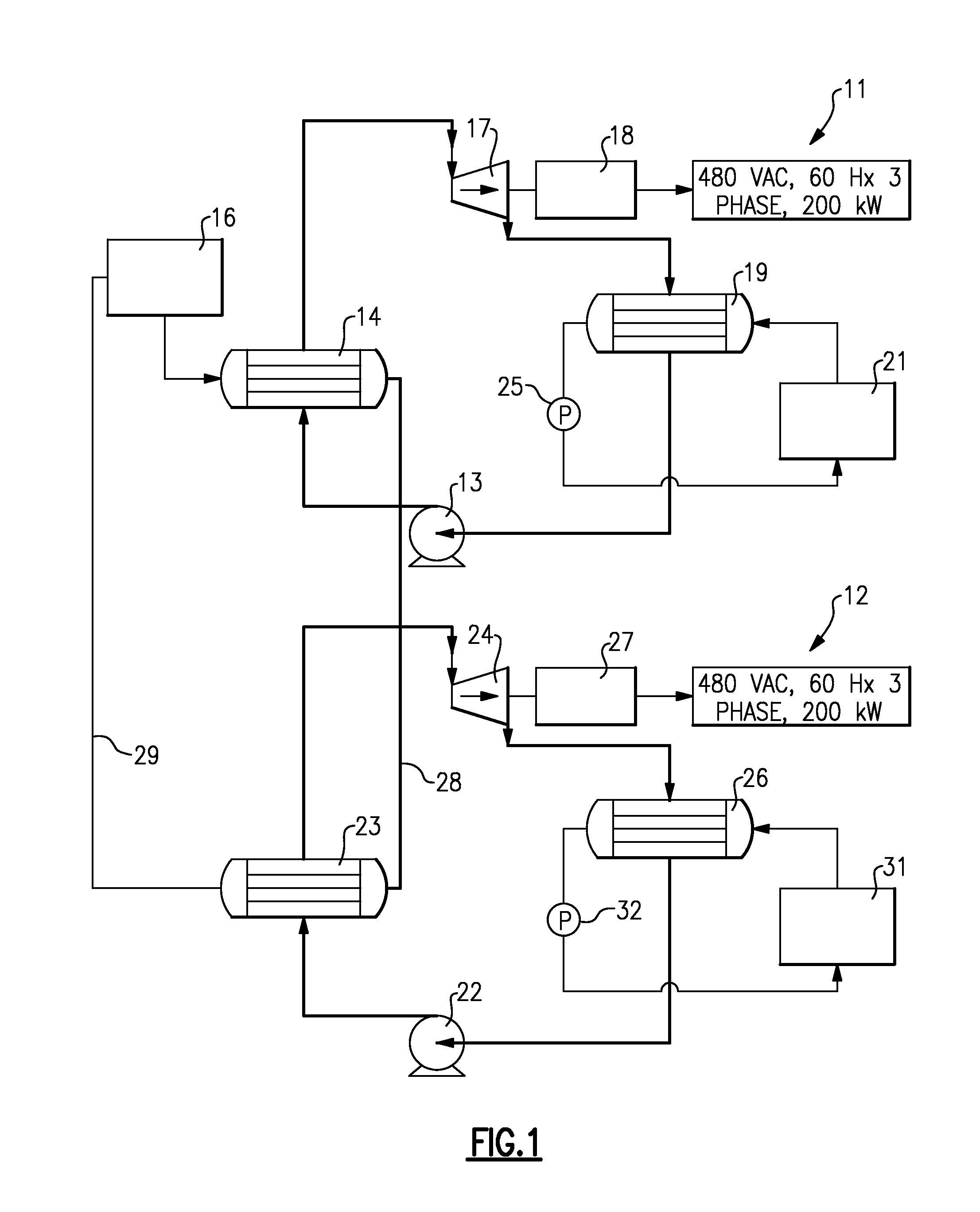
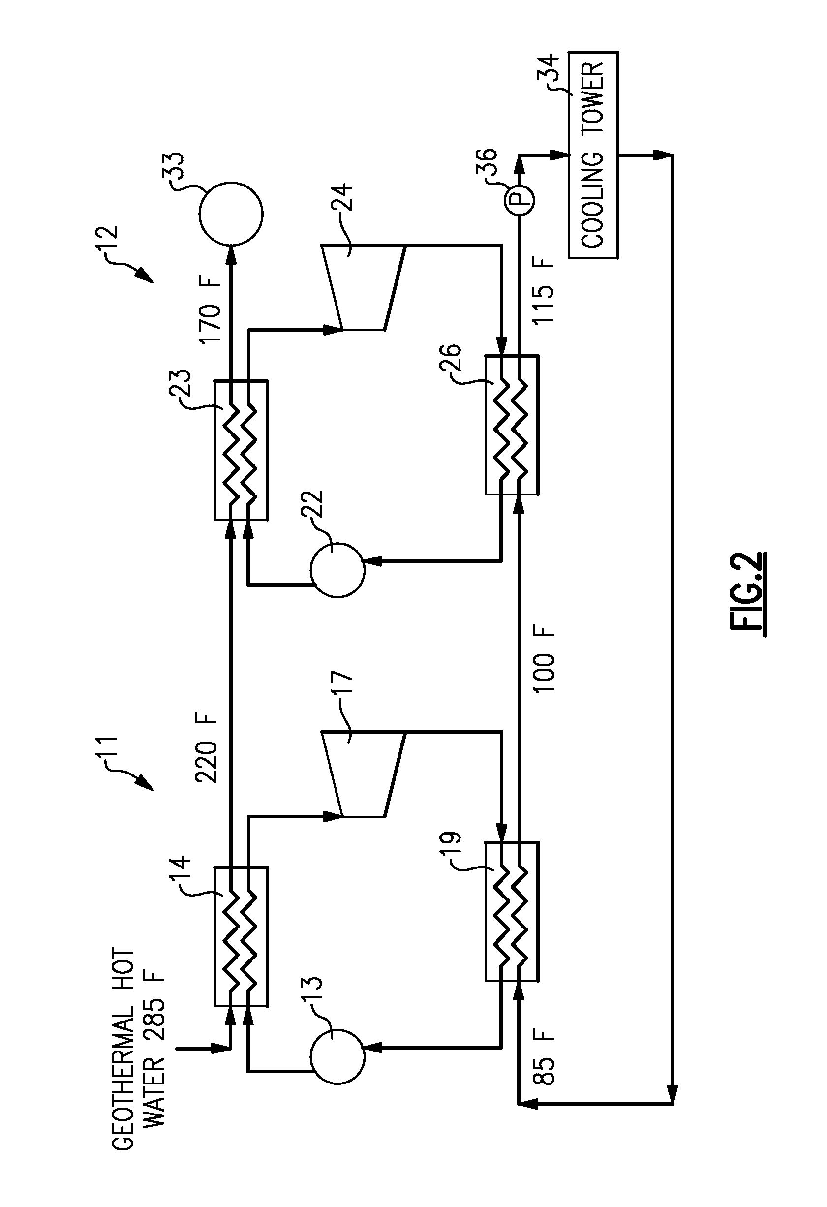
[0010]Shown in FIG. 1 is a pair of organic rankine cycle systems 11 and 12 arranged to operate in accordance with the prior art. The first ORC system 11 includes, in serial, working fluid flow relationship, a pump 13, an evaporator 14, a turbine 17, and a condenser 19. The working fluid is any suitable organic refrigerant such as R-245fa. The refrigerant is pumped by the pump 13 to an evaporator 14 where it is heated by hot water from a geothermal heat source 16. The resulting superheated vapor then passes to the turbine 17 for driving a generator 18 to produce electrical power. The resulting lower energy vapor then passes to the condenser 19 where it is condensed by giving up heat to the cooling water circulating through the condenser 19 from a heat sink 21. The condensate then passes to the pump 13 to complete the cycle. The heat sink 21 may be a cooling tower or a pond or river, to the condenser 19, and a pump 25 drives the cooling fluid to the heat sink 21.

[0011]The second ORC s...


PUM


Abstract

A pair of organic rankine cycle systems are connected in series with the geothermal fluid passing first through an evaporator of the first system and then through an evaporator of the second system before returning to a sink. Similarly, the cooling tower is arranged to provide cooling water to pass first through the condenser in one system and then through the condenser of the other system, to reduce the total flow required and the size of associated cooling hardware.

Description

TECHNICAL FIELD [0001]This invention relates generally to vapor expansion systems and, more particularly, to additional efficiency improvements to a cascaded organic rankine cycle systems.BACKGROUND OF THE DISCLOSURE [0002]The well known closed rankine cycle comprises a boiler or evaporator for the evaporation of a motive fluid, a turbine fed with vapor from the boiler to drive the generator or the load, a condenser for condensing exhaust vapors from the turbine and a means such as a pump, for recycling the condensed fluid to the boiler.[0003]Such rankine cycle systems are commonly used for the purpose of generating electrical power that is provided to a power distribution system, or grid, for residential and commercial use across the country. A source of heat to the boiler can be of any form such as fossil fuel, nuclear power, or waste heat from internal combustion engines, for example. Because of recent concerns for the environment, and because of the rapid rise in the price of pe...

Claims


Application Information

Patent Timeline
IPC IPC(8): F01K25/00F01K27/00
CPCF01K25/10F01K9/003
Inventor BREEN, SEAN P.COLLINS, SHAWN T.WOOLLEY, LANCE D.
Owner UNITED TECH CORP
Why Eureka
Try Eureka