Reactor containment vessel cooling system, reactor containment vessel, and reactor containment vessel cooling method

a technology for containment vessels and reactors, which is applied in the direction of domestic cooling apparatus, greenhouse gas reduction, nuclear elements, etc., can solve the problems of accidental loss of the power supply responsible for the entire nuclear facility, difficult to completely eliminate the possibility of releasing radioactive materials into the atmosphere along with water vapor and other gases, and the cooling method is not acceptable. to achieve the effect of preventing the cooling capability and structural integrity of the reactor containment vessel cooling system from decreasing

Inactive Publication Date: 2011-12-29
KK TOSHIBA
View PDF14 Cites 16 Cited by
  • Summary
  • Abstract
  • Description
  • Claims
  • Application Information

AI Technical Summary

Benefits of technology

[0026]The present invention can prevent the cooling capability and structural integrity of a reactor containment vessel cooling sys

Problems solved by technology

In the cooling method, fission products and other radioactive nuclides contained in the water vapor and gases to be released into the atmosphere are basically separated in advance, but it is difficult to completely eliminate the possibility of releasing part of the radioactive materials into the atmosphere along with the water vapor and other gases.
Therefore, there is an opinion that su

Method used


Image

  • Reactor containment vessel cooling system, reactor containment vessel, and reactor containment vessel cooling method
  • Reactor containment vessel cooling system, reactor containment vessel, and reactor containment vessel cooling method
  • Reactor containment vessel cooling system, reactor containment vessel, and reactor containment vessel cooling method

Examples


first embodiment

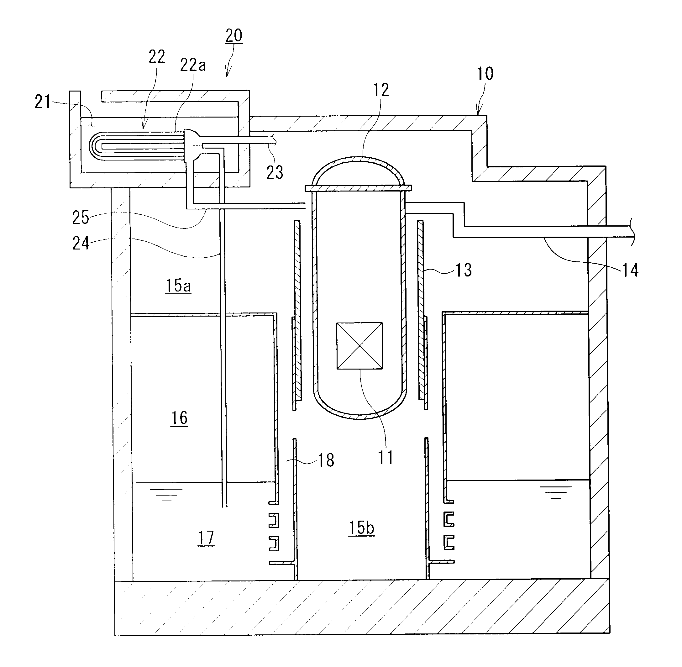
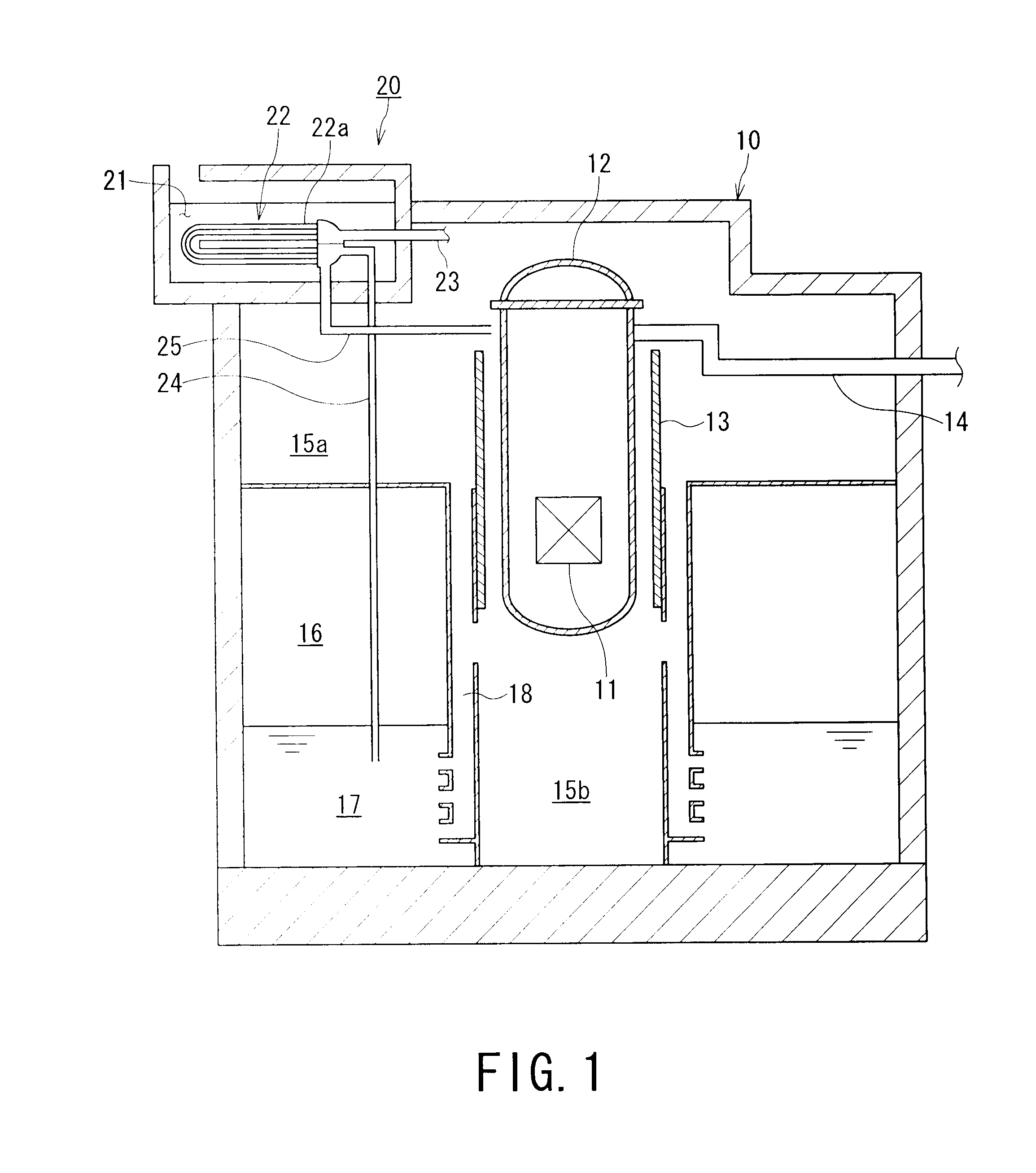
[0034]FIG. 1 is a front sectional view showing a first embodiment of a reactor containment vessel cooling system according to the present invention.

[0035]A reactor containment vessel cooling system 20 according to the first embodiment is provided inside or outside a reactor containment vessel 10.

[0036]The reactor containment vessel 10 is provided so as to surround reactor pressure vessel 12 that accommodates a core 11, a react or shielding wall 13 and other reactor structures or components. The reactor containment vessel 10 has a structure capable of preventing fission products from being released into the atmosphere even in a case where a primary steam tube 14 or any of her component is broken and hence reactor water in the reactor pressure vessel 12 is lost and a fuel is melt or damaged.

[0037]The reactor containment vessel 10 includes a dry well 15 (upper dry well 15a and lower dry well 15b) that forms a space for accommodating the reactor pressure vessel 12 and a suppression cham...

second embodiment

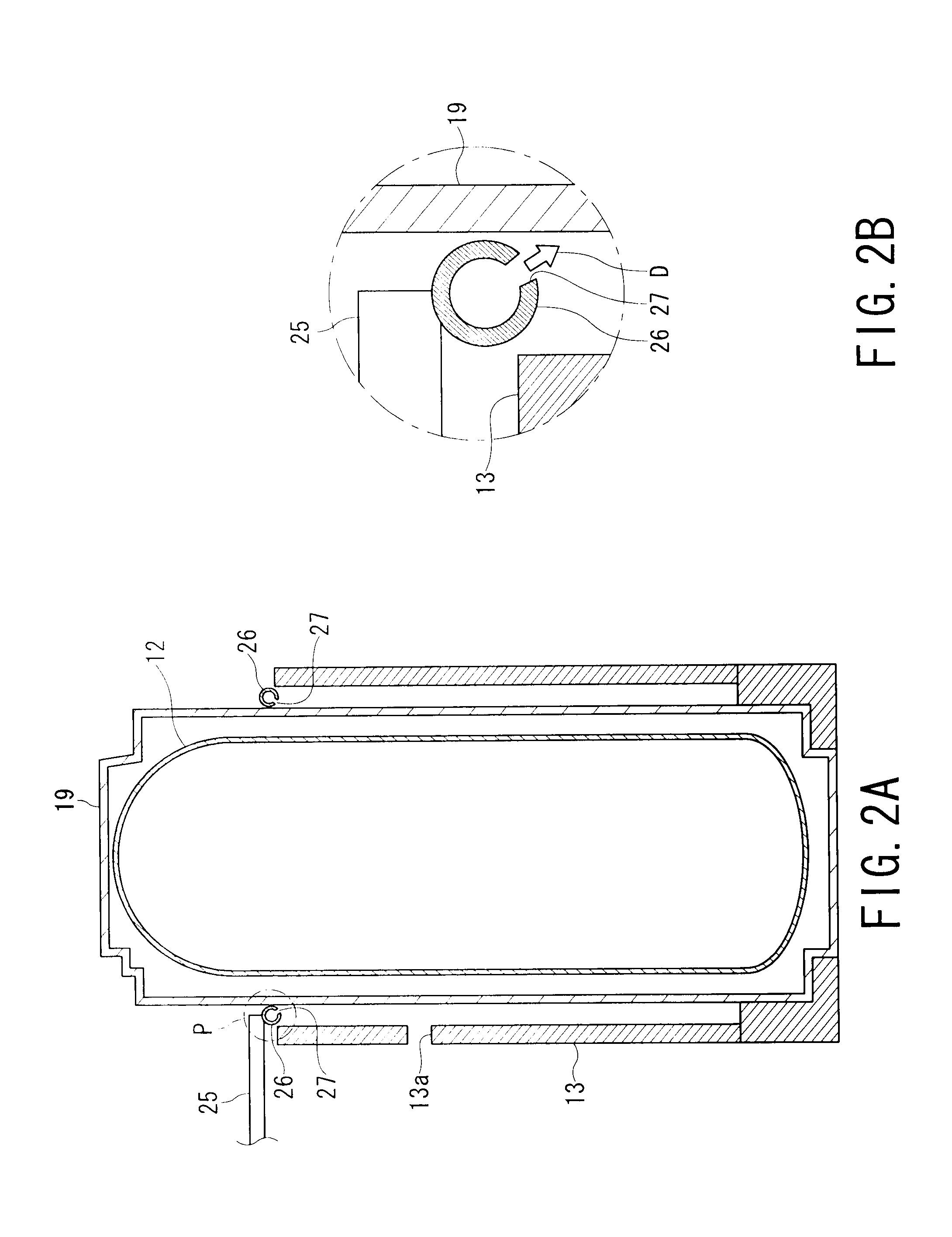
[0058]FIG. 5 is an enlarged sectional view of a key portion showing a second embodiment of the reactor containment vessel cooling system according to the present invention. The present embodiment is an example in which the condensate drain pipe 25 in the reactor containment vessel cooling system 20 in the first embodiment is configured differently. In the following descriptions, components or members similar to those in the first embodiment are added with the same reference numerals, and components different from those in the first embodiment or added thereto are labeled with “A” in the following description.

[0059]A condensate drain pipe 25A in the present embodiment includes a header tube 26A.

[0060]The header tube 26A is formed of a ring-shaped pipe through which condensate extracted from the heat exchanger 22 (see FIG. 1) flows, as in the first embodiment, but is embedded in the thermally insulating member 19 and circumferentially surrounds the reactor pressure vessel 12.

[0061]The...

third embodiment

[0067]FIG. 6 is an enlarged sectional view of an essential portion representing a third embodiment of the reactor containment vessel cooling system 20B according to the present invention. The present embodiment is an example in which the condensate discharge parts 27A in the reactor containment vessel cooling system 20A in the second embodiment are configured differently. In the following descriptions, components or members similar to those in the second embodiment are added with the same reference numerals, and components different from those in the second embodiment or added thereto are labeled with “B” in the following description.

[0068]The reactor containment vessel cooling system 20B includes nozzles 29B, as shown in FIG. 6. Each of the nozzles 29B extends from the edge of the corresponding discharge port 27A (see FIG. 5) in the second embodiment and forms a discharge portion through which the condensate extracted from the heat exchanger 22 (see FIG. 1) is discharged.

[0069]The ...


PUM


Abstract

A reactor containment vessel cooling technology for preventing the cooling capability and structural integrity of a reactor containment vessel cooling system from decreasing by lowering the temperature of water vapor and gases acquired by the reactor containment vessel cooling system is provided. Based on the technology, the present invention provides a reactor containment vessel cooling system that acquires water vapor in a reactor containment vessel by using water vapor pressure in the vessel as a drive force, condenses the acquired water vapor into condensate, and cools the reactor containment vessel with the condensate. The reactor containment vessel cooling system includes a heat exchange pool 21 that is arranged apart from a dry well 15 and a suppression chamber 16 in the reactor containment vessel 10 and stores a medium for cooling water vapor, a heat exchanger 22 that is immersed in the heat exchange pool 21, acquires water vapor from the dry well 15 in the reactor containment vessel 10, and performs heat exchange between the eater vapor and the cooling medium in the heat exchange pool 21 to generate condensate, and a condensate drain pipe 25 that extracts the condensate from the heat exchanger 22 and guides and discharges the condensate toward a reactor pressure vessel 12.

Description

TECHNICAL FIELD[0001]The present invention relates to a reactor containment vessel cooling technology for maintaining safety of the environment around a reactor by removing decay heat generated when reactor water is accidentally lost, and particularly, to a reactor containment vessel cooling technology for producing emergency cooling water by using water vapor pressure in a reactor containment vessel as a drive force, and the present invention includes a reactor containment vessel cooling system, a reactor containment vessel, and a reactor containment vessel cooling method.BACKGROUND ART[0002]A nuclear reactor includes an emergency core cooling system and a decay heat removing system for maintaining safety of the environment around the reactor by cooling the inside of a reactor containment vessel with water to remove decay heat in case reactor water is accidentally lost. In addition, in consideration of a case where the emergency core cooling system or the decay heat removing system...

Claims


Application Information

Patent Timeline
IPC IPC(8): F25D31/00
CPCG21C9/004Y02E30/40G21C15/18Y02E30/30
Inventor TAHARA, MIKANAKAMARU, MIKIHIDEMURASE, AKIRAHAMAZAKI, RYOICHI
Owner KK TOSHIBA
Why Eureka
Try Eureka