Constant-residual-pressure valve

a constant-residual-pressure valve and valve seat technology, which is applied in the direction of valve housings, fluid pressure control, instruments, etc., can solve the problems of cavitation generating strong impact, noise and vibration, damage to the pressure holding performance of the constant-residual-pressure valve may also be deteriorated, so as to reduce the speed of fuel flowing between the valve body and the valve seat, reduce noise and vibration, and reduce vibration

Inactive Publication Date: 2011-12-29
DENSO CORP +1
View PDF25 Cites 30 Cited by
  • Summary
  • Abstract
  • Description
  • Claims
  • Application Information

AI Technical Summary

Benefits of technology

[0008]According to the present invention, a constant-residual-pressure valve is disposed in a communication passage connecting a high-pressure fuel passage through which pressurized fuel flows with a low-pressure fuel passage through which the fuel flows toward a high-pressure pump. The constant-residual-pressure valve includes a valve body, a biasing member and a downstream-orifice. The valve body is capable of sitting on a valve seat formed on an inner wall surface of the communication passage. The valve body prohibits a fuel flow from the low-pressure fuel passage to the high-pressure fuel passage in a case that the valve body sits on the valve seat. The valve body allows a fuel-flow from the high-pressure fuel passage to the low-pressure fuel passage in a case that the valve body is apart from the valve seat. The biasing means biases the valve body toward the valve seat with a specified biasing force. A flow passage area of the downstream-orifice is smaller than that of a passage upstream of the valve seat.
[0009]When the valve body moves apart from the valve seat, the fuel flows into the communication passage. Since the fuel-flow

Problems solved by technology

Such cavitation generates strong impact, noise, and vibration.
It is likely that the valve body and the valve seat are damaged due to the cavitation corrosion (erosion corrosion).
If the valve body and the valve seat are damaged due to the cavitation corrosion, the oil-tightness between the valve body and the valve s

Method used


Image

  • Constant-residual-pressure valve
  • Constant-residual-pressure valve
  • Constant-residual-pressure valve

Examples


first embodiment

[0038][First Embodiment]

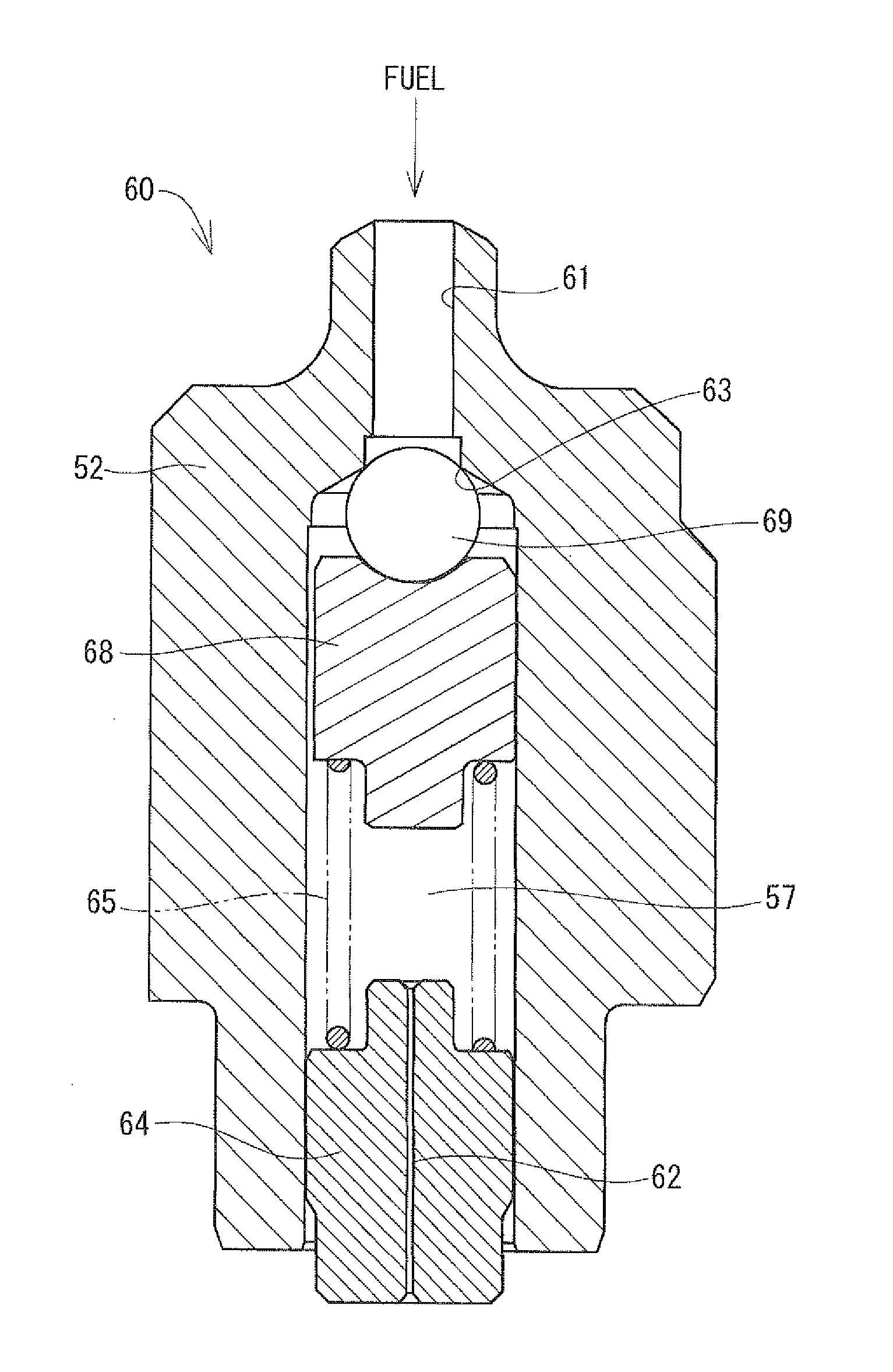
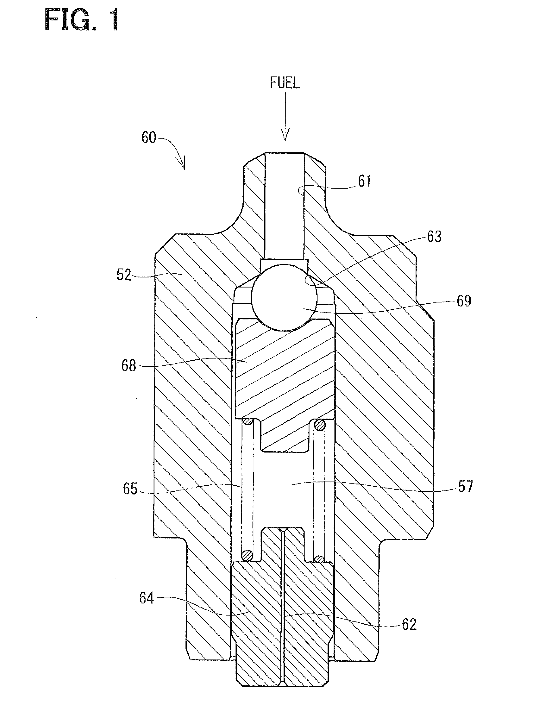
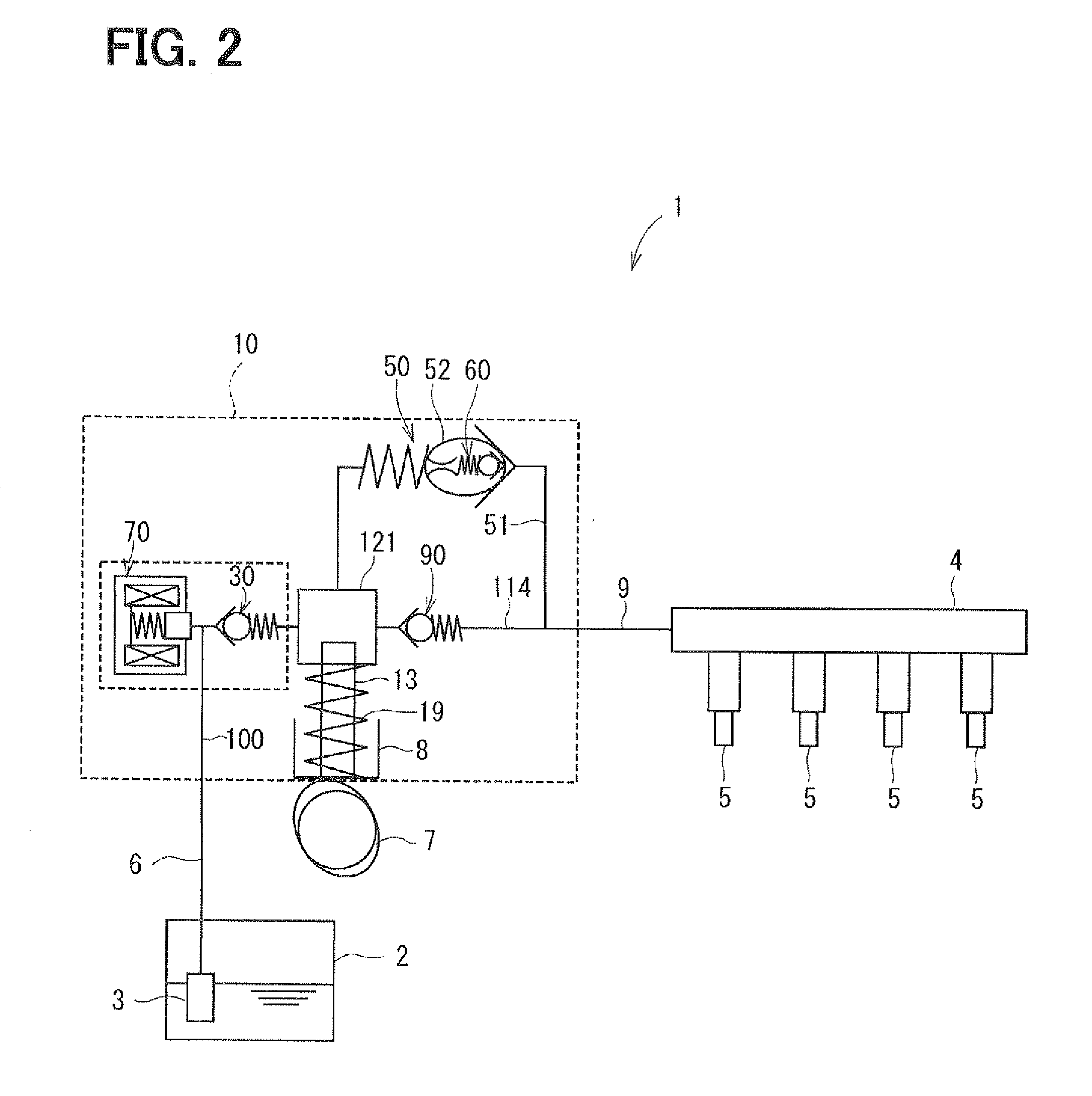
[0039]Referring to FIGS. 1 to 5, a first embodiment of the invention will be described. As shown in FIG. 2, a constant-residual-pressure valve 60 is provided to a high-pressure pump 10 which is used in a fuel-supply system 1 of a direct injection engine. In the fuel-supply system 1, a low-pressure pump 3 pumps up fuel from a fuel tank 2. The pumped fuel is introduced into a supply passage 100 of the high-pressure pump 10 through a low-pressure fuel pipe 6. The high-pressure pump 10 has a plunger 13 which axially reciprocates to pressurize the fuel in a pressurization chamber 121. The pressurized fuel is discharged into a discharge passage 114. The pressurized fuel is introduced into a high-pressure fuel pipe 9 and is accumulated in a delivery pipe 4. Then, the high-pressure fuel accumulated in the delivery pipe 4 is injected into each cylinder through a fuel injector 5.

[0040]A relief valve 50 is provided in a communication passage 51 which connects the discha...

second embodiment

[0072][Second Embodiment]

[0073]Referring to FIG. 6, a second embodiment of the constant-residual-pressure valve will be described. The constant-residual-pressure valve includes an upstream-orifice 66 in the passage 61 upstream of the valve seat 63. A flow passage area of the upstream-orifice 62 is greater than that of the downstream-orifice 62. The flow passage areas of the downstream-orifice 62 and the upstream-orifice 66 are enough to maintain the pump efficiency of the high-pressure pump 10. That is, when the plunger 13 slides down to reduce the pressure in the pressurization chamber 121, the fuel pressure in the delivery pipe 4 receives less influence from the fuel flowing into the pressurization chamber 121 from the discharge passage 114.

[0074]When the valve body 69 moves away from the valve seat 63, the fuel pressure is rapidly accumulated in the inner passage 57 between the valve body 69 and the downstream-orifice 62. Thus, the differential pressure between the passage 61 and...

third embodiment

[0075][Third Embodiment]

[0076]Referring to FIG. 7, a third embodiment of the constant-residual-pressure valve will be described. The spring-stopper 64 has a concave portion 80 downstream of the downstream-orifice 62. Since the velocity of the fuel flowing through the downstream-orifice 62 is high, it is likely that the cavitation is generated around an outlet of the downstream-orifice 62. However, since the flow passage area of the concave portion 80 is greater than that of the downstream-orifice 62, the velocity of the fuel flowing through the concave portion 80 is decreased. Thus, in the present embodiment, the cavitation generated in the downstream-orifice 62 can be reduced in the concave portion 80. It is restricted that the cavitation corrosion is generated on the relief spring 54 and the adjustment pipe 53. Besides, by forming the concave portion 80 in the spring-stopper 64, the length of the downstream-orifice 62 is made shorter. The manufacturing cost of the downstream-orifi...


PUM


Abstract

A constant-residual-pressure valve is disposed in a communication passage connecting a high-pressure fuel passage through which pressurized fuel flows with a low-pressure fuel passage through which the fuel flows toward a high-pressure pump. The constant-residual-pressure valve includes a valve body, a spring, and a spring stopper. The valve body can sit on a valve seat formed in an inner passage. The spring biases the valve body toward the valve seat. The spring stopper has a downstream-orifice of which flow passage area is smaller than that of a passage upstream of the valve seat. Thereby, cavitation between the valve body and the valve seat is less generated.

Description

CROSS-REFERENCE TO RELATED APPLICATION[0001]This application is based on Japanese Patent Application No.2010-147600 filed on Jun. 29, 2010, the disclosure of which is incorporated herein by reference.FIELD OF THE INVENTION[0002]The present invention relates to a constant-residual-pressure valve which is applied to a fuel supply system of a direct injection engine.BACKGROUND OF THE INVENTION[0003]Conventionally, a fuel supply system which supplies fuel to a direct injection engine is equipped with a high-pressure pump for pressurizing the fuel. The fuel discharged from the high-pressure pump is accumulated in a delivery pipe and is injected to a cylinder through an injector.[0004]JP-2009-121395A (WO-2009 / 063306A1) shows a constant-residual-pressure valve which is disposed in a fuel passage connecting a pressurization chamber of the high-pressure pump and a delivery pipe. When a differential fuel pressure between the delivery pipe and the pressurization chamber exceeds a specified pre...

Claims


Application Information

Patent Timeline
IPC IPC(8): F16K27/02
CPCF02M55/025F02M59/447F02M63/0054F16K15/026F02M63/005F16K15/044F16K27/0209G05D16/103F16K27/029F16K15/028G05D16/0402
Inventor OIKAWA, SHINOBUTOMITA, HIROKUNI
Owner DENSO CORP
Why Eureka
Try Eureka