Method And Apparatus For Dry Casting Concrete Blocks Having A Decorative Face

a technology of dry casting concrete and decorative faces, which is applied in the direction of dough shaping, manufacturing tools, applications, etc., can solve the problems of inability to use molds for casting additional blocks and inability to achieve deeper patterns, and achieve the effect of reducing wear

Inactive Publication Date: 2011-12-29
ROSETTA HARDSCAPES
View PDF8 Cites 19 Cited by
  • Summary
  • Abstract
  • Description
  • Claims
  • Application Information

AI Technical Summary

Benefits of technology

[0011]According to another feature of the invention, since the face of the block is cast on a side of the cavity, the shoe and the pallet form the top and bottom of the block. For a standard block, the top and bottom may be interchangeable. The shoe may be shaped to form a rear lip extending above the back edge of the block. When the blocks are inverted and stacked in rows to form a wall, the rear lip may position the upper blocks slightly behind the adjacent lower blocks for providing a stable, sloping wall.
[0012]According to another feature of the invention, the insert which creates the face of the cast blocks is positioned on the steel pallet before the pallet and the form are brought together either by raising the pallet or by lowering the form, or by moving both. Preferably, the insert is made from a resilient rubber like material, such as a polyurethane material. Magnets may be embedded in the bottom of the insert to help maintain the position of the insert on the steel pallet, while permitting the insert to slide on the pallet for alignment with the form. Further, a tough, wear resistant layer may be secured to the bottom of the insert to reduce wear when the cast blocks and the insert are pushed from the pallet. When viewed from the top or bottom, the insert is generally rectangular, with two opposing ends which will abut the form and two opposing sides which will open into the mold cavities for forming the faces of two blocks. The ends of the blocks are slightly angled towards each other and the sides of the blocks are slightly angled towards each other. When the insert and the form are brought together, the ends are engaged by complementary angled grooves in the form so that the insert will move, as necessary, on the pallet to align with the form.

Problems solved by technology

During the cure time, the mold cannot be used for casting additional blocks.
These blocks frequently have vertical passages which reduce the weight of the blocks and are not decorative.
Deeper patterns have not been achievable due to problems with the relatively soft uncured block breaking when separating the block from the mold which forms the decorative surface.

Method used


Image

  • Method And Apparatus For Dry Casting Concrete Blocks Having A Decorative Face
  • Method And Apparatus For Dry Casting Concrete Blocks Having A Decorative Face
  • Method And Apparatus For Dry Casting Concrete Blocks Having A Decorative Face

Examples


Embodiment Construction

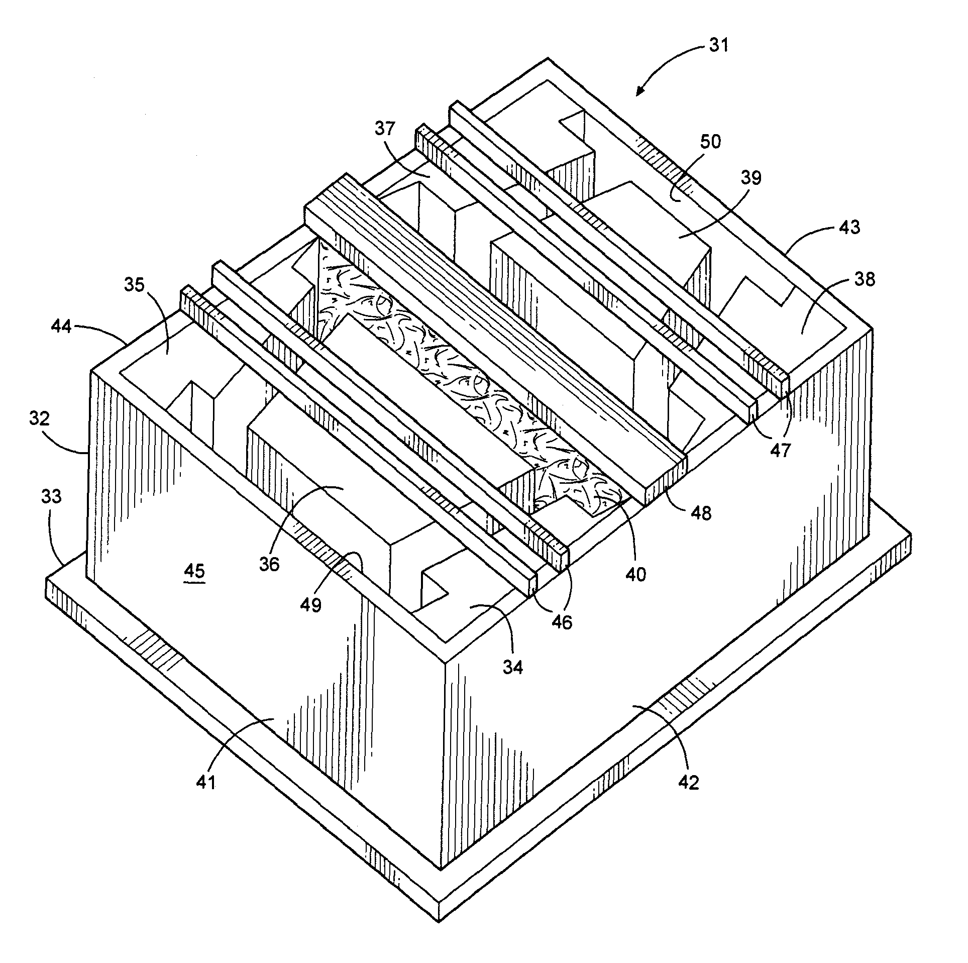
[0030]In a conventional dry casting block machine, a form for shaping sides of the block is positioned on a steel pallet or other rigid support surface. The form has an open top and an open bottom which is closed by the support surface and may have a single mold cavity for casting a single block, or may have a plurality of mold cavities for simultaneously casting a number of concrete blocks. Each cavity is then filled with a dry casting concrete mixture. Typically, the form is vibrated to distribute the concrete mixture in the cavities as the form is filled. A head assembly carrying a shoe is mounted on the machine to be positioned above each cavity. The shoe has the same shape and size as the mold cavities so that it can be lowered into the upper openings into the cavities. A shoe is then lowered into the top of each form cavity and a high pressure is applied to each shoe for simultaneously pressing and compacting the dry cast concrete in each cavity. The applied pressure may be, f...


PUM

PropertyMeasurementUnit
flexibleaaaaaaaaaa
areaaaaaaaaaaa
surface areaaaaaaaaaaa

Abstract

A method and apparatus for dry casting concrete wall blocks having a decorative face. The blocks are cast in a mold including a form, a flexible insert and a steel pallet. Magnets hold the insert on the pallet while permitting the insert to slide on the pallet into alignment with the form when the form and pallet are moved together. The insert creates a decorative face on one or more simultaneously cast blocks. After the blocks are cast, the uncured blocks and the insert are moved together from the form and transferred to a curing area. After the blocks cure, they are separated from the insert. Preferably, additional concrete mix is provided adjacent the insert prior to compacting to avoid voids in the block face. Optionally, the shoe which compacts the concrete mix may be shaped to impart a lip adjacent a back edge of the block.

Description

CROSS-REFERENCE TO RELATED APPLICATIONS[0001]Applicants claim priority to U.S. Provisional Patent Application Ser. No. 61 / 357,963 filed Jun. 23, 2010.STATEMENT REGARDING FEDERALLY SPONSORED RESEARCH OR DEVELOPMENT[0002]Not Applicable.TECHNICAL FIELD[0003]The invention relates to a method and apparatus for dry casting concrete blocks having decorative faces.BACKGROUND OF THE INVENTION[0004]Two methods are commonly used for casting concrete blocks: wet casting and dry casting. In a wet casting process, liquid concrete is poured into a block mold cavity and remains in the cavity until the concrete has cured sufficiently to permit removal without damage to the cast block. During the cure time, the mold cannot be used for casting additional blocks. When one or more surfaces of the block are to be decorative, the bottom of the cavity may be lined with, for example, a urethane insert shaped to impart a desired texture or decoration to the cast block. This process may be used, for example, ...

Claims


Application Information

Patent Timeline
Patent Type & Authority Applications(United States)
IPC IPC(8): B28B7/30
CPCB28B7/0014B28B7/002B28B7/007B28B7/0097B28B7/241E02D29/025B28B7/0064B28B7/0079B28B7/20B28B7/366B28B3/02B28B7/24B28B7/00
Inventor MANTHEI, JEREMY L.
Owner ROSETTA HARDSCAPES
Why Eureka
Try Eureka