Non-contact charge and communication system

Inactive Publication Date: 2011-12-29
SONY CORP
View PDF5 Cites 23 Cited by
  • Summary
  • Abstract
  • Description
  • Claims
  • Application Information

AI Technical Summary

Benefits of technology

The embodiment of the present invention can optimize both of non-conta

Problems solved by technology

However, in the system in which one coil is shared by the non-contact communication system and the non-contact charge system and non-contact communication and non-contact charge are carried out separatel

Method used


Image

  • Non-contact charge and communication system
  • Non-contact charge and communication system
  • Non-contact charge and communication system

Examples


first embodiment (

1. First Embodiment (first configuration example of non-contact charge and communication system)

second embodiment (

2. Second Embodiment (second configuration example of non-contact charge and communication system)

first embodiment

1. First Embodiment

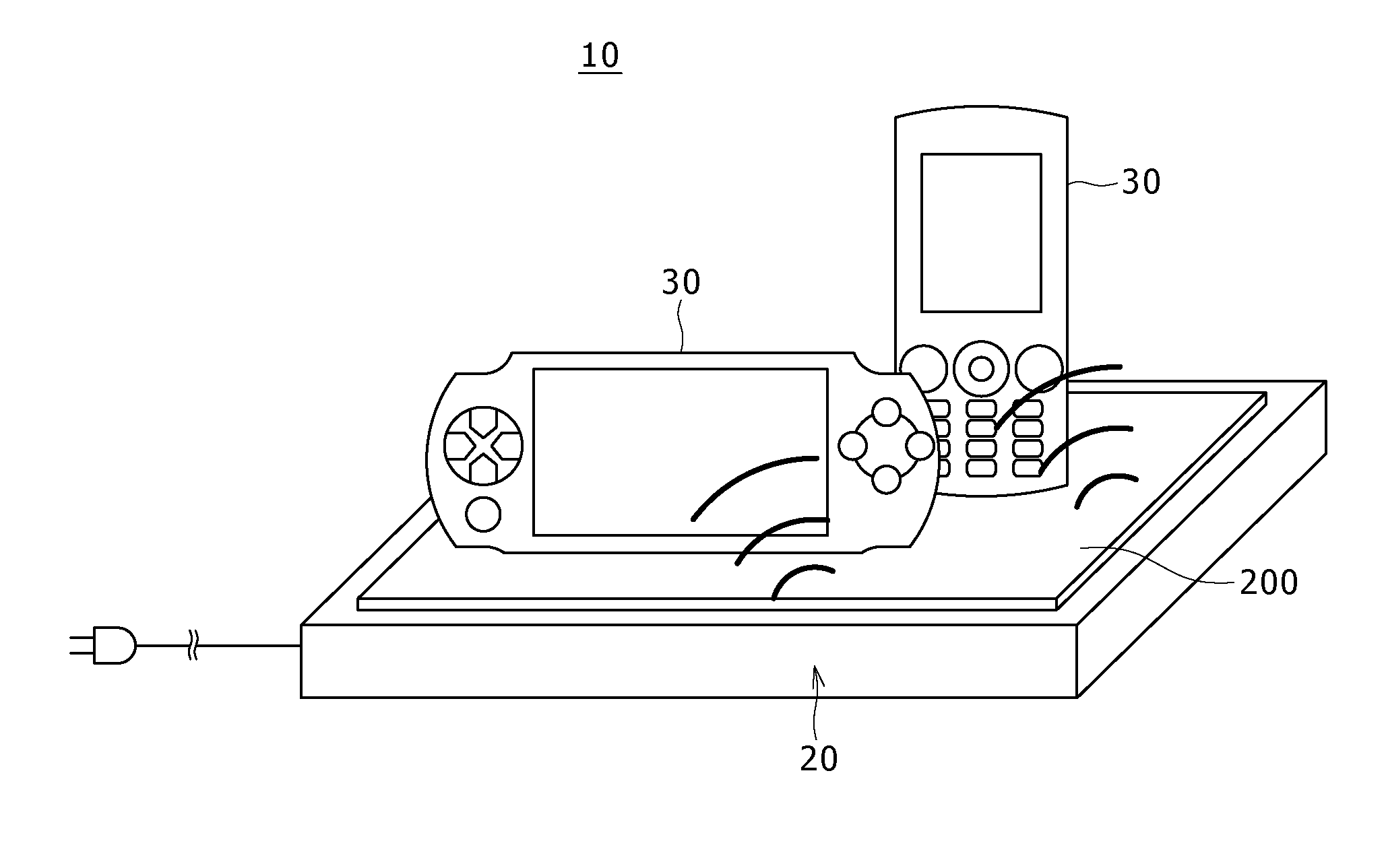
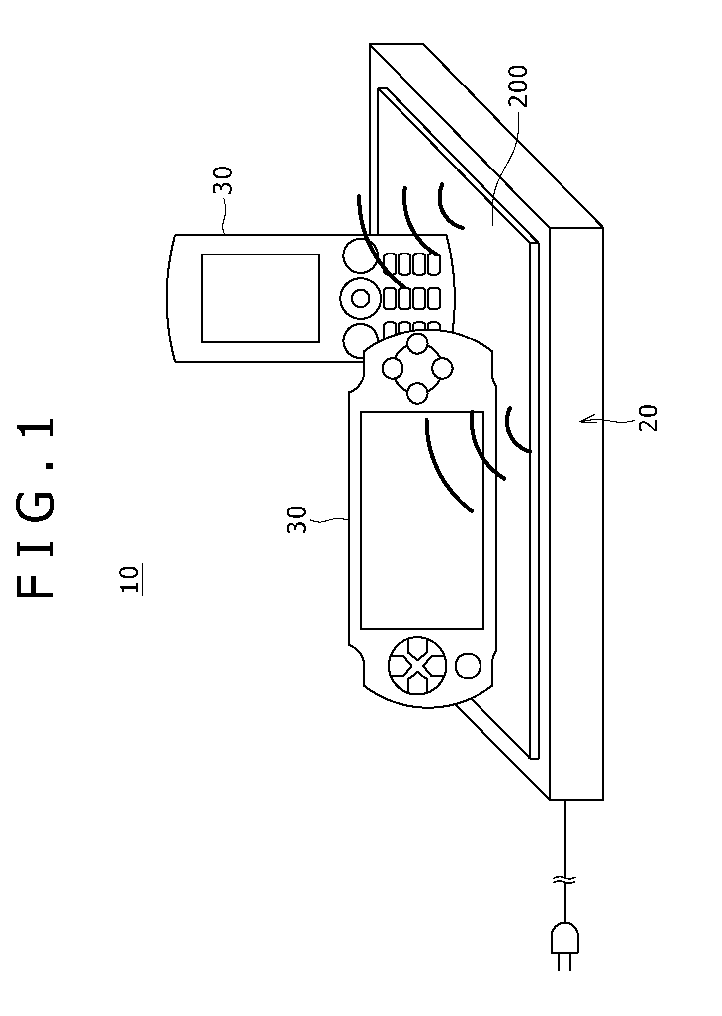
FIG. 1 is a diagram schematically showing the whole configuration of a non-contact charge and communication system according to a first embodiment of the present invention.

[Basic Configuration of Non-Contact Charge and Communication System]

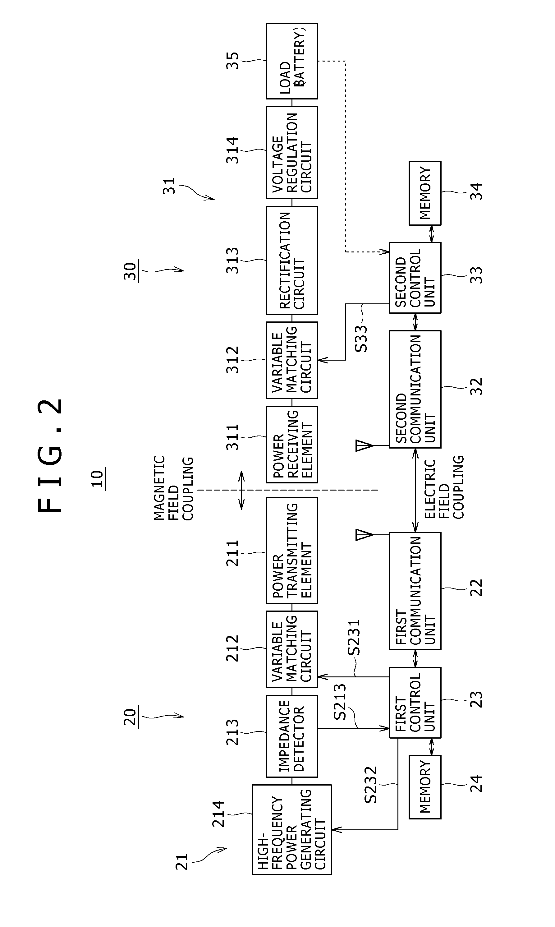
This non-contact charge and communication system 10 has non-contact charge apparatus 20 and power receiving apparatus 30 that can be driven by a battery.

Basically, the non-contact charge apparatus 20 is formed into a box shape or a mat shape and has a function to carry out non-contact communication and non-contact charge in accordance with the condition to be described in detail later with the power receiving apparatus 30 that is disposed or placed at a position within the range in which charge and communication are possible for a charge of the battery.

The non-contact charge apparatus 20 has a station 200 that is the part on which the power receiving apparatus 30 is disposed.

The power receiving apparatus 30 is formed of a portab...


PUM


Abstract

Disclosed herein is a non-contact charge and communication system including: non-contact charge apparatus configured to include a power transmitting device that transmits power for a charge by magnetic field coupling and a first communication unit that carries out non-contact communication by electric field coupling; and power receiving apparatus configured to include a power receiving device that receives power transmitted from the non-contact charge apparatus based on a magnetic field resonance relationship and a second communication unit capable of non-contact communication with the first communication unit by electric field coupling, and charge a battery by received power. The non-contact charge apparatus includes a first control unit, and the power receiving apparatus includes a storage unit, and a second control unit.

Description

BACKGROUND OF THE INVENTION1. Field of the InventionThe present invention relates to a non-contact charge and communication system including a non-contact charge system and a wireless communication system that transmit and receive power in a non-contact (wireless) manner.2. Description of the Related ArtThe electromagnetic induction system is known as a system for non-contact (wireless) supply of power.Furthermore, in recent years, wireless power feed and charge systems employing a system called the magnetic field resonance system based on the electromagnetic resonance phenomenon are attracting attention.Presently, in the non-contact power feed system based on the electromagnetic induction system, which has been already widely used, the power feed source and the power feed target (power receiving side) have to share magnetic flux. Therefore, the power feed source and the power feed target have to be disposed very close to each other for power sending with high efficiency, and axis a...

Claims


Application Information

Patent Timeline
IPC IPC(8): H02J7/00
CPCH02J7/025H04B5/0075H04B5/0037H04B5/0031H02J50/10H02J7/00034H02J50/60H02J50/90H02J50/80H02J50/12
Inventor WASHIRO, TAKANORI
Owner SONY CORP
Why Eureka
Try Eureka