Touch panel

a touch panel and panel technology, applied in the field of touch panels, can solve the problems of affecting the driving of the touch panel, no means of shielding noise, and emi (electro-magnetic interference) taken place,

Active Publication Date: 2011-12-29
LG DISPLAY CO LTD
View PDF11 Cites 91 Cited by
  • Summary
  • Abstract
  • Description
  • Claims
  • Application Information

AI Technical Summary

Benefits of technology

[0023]An object of the present invention is to provide a touch panel which can detect a touch securely without being affected by drive of an underlying display panel and shield external static electricity securely.

Problems solved by technology

Consequently, at the time noise caused by external static electricity infiltrates, there is no means for shielding the noise.
And, when the touch panel is attached to a display device (not shown), such as the liquid crystal display panel, a position of the touch panel through which the routing lines 31 pass becomes to match with a circuit at the periphery of the display device, causing a problem of EMI (Electro-Magnetic Interference) taken place when the underlying display device is driven.
Thus, the related art touch panel has the following problems.
The routing lines exposed from the peripheral region of the touch panel causes noise when the external static electricity infiltrates thereto, affecting driving of the touch panel.
And, when the touch panel is attached to the liquid crystal display device, EMI interference takes place at a portion the circuit of the liquid crystal panel overlaps with the routing lines, causing malfunction of the touch.

Method used


Image

  • Touch panel
  • Touch panel
  • Touch panel

Examples


first embodiment

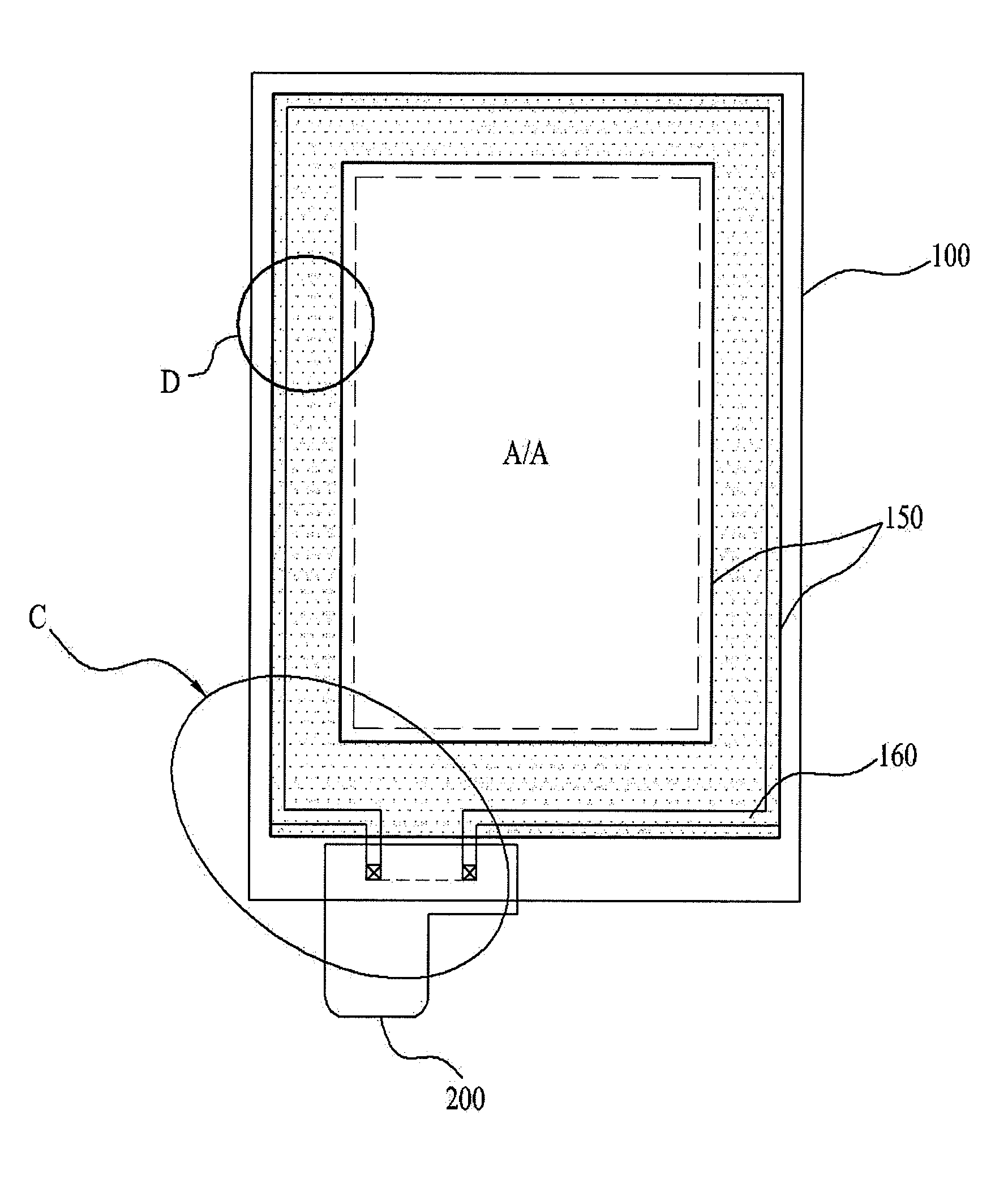
[0086]Referring to FIG. 9, different from the first embodiment, the touch panel has double transparent conductive layers 150 formed over and under the guide ring line 160, respectively.

[0087]The transparent conductive layer 150 includes a first transparent conductive layer 350a positioned under the guide ring line 160, and a second transparent conductive layer 350b over the guide ring line 160 in contact with the guide ring line 160 through contact holes formed through the second insulating film 355 and the first insulating film 353 by removing predetermined portions of the second insulating film 355 and the first insulating film 353.

second embodiment

[0088]In this instance, the first electrodes 110 and the second electrodes 120 can also be formed on layers different from each other respectively and matched to the first and second transparent conductive layers 350a and 350b to form each of the electrodes as one unit without providing additional connection patterns. Depending on cases, as described before, the first electrodes 110 and the second electrodes 120 can be formed on the first transparent conductive layer 350a or the second transparent conductive layer 350b at a time, with a bridge structure (A second connection pattern at a layer different from the second electrode) described in the first or second embodiment formed at each crossed portion of the first electrodes 110 and the second electrodes 120 for preventing short taking place at the crossed portions.

third embodiment

[0089]In the third embodiment, since the transparent conductive layer 150 shields the periphery of the touch panel doubly, enabling secure prevention of infiltration of the external static electricity and secure shielding of the electro-magnetic interference from the underlying display panel.

[0090]FIG. 10 illustrates a section of a display panel having an embedded touch panel of the present invention applied thereto, in which the touch panel of the present invention is applied to a liquid crystal panel.

[0091]Referring to FIG. 10, the display panel having an embedded touch panel shows an example in which the touch panel in the second preferred embodiment is applied to a liquid crystal panel 1000, with the touch panel overturned.

[0092]The liquid crystal panel 1000 includes first and second substrates 400 and 500 opposite to each other, a liquid crystal layer 450 filled between the first and second substrates 400 and 500, and first and second polarizing plates 510 and 520 attached to o...


PUM


Abstract

The present invention relates to a touch panel which can detect touch securely without being affected by drive of an underlying display panel and shield external static electricity, securely, the touch panel includes a substrate having an active region and a peripheral region surrounding the active region; a plurality of first electrodes and second electrodes formed on the active region in a row direction and a column direction, respectively; a plurality of pad electrodes on one side of the peripheral region; routing lines for connecting ends of the first electrodes and the second electrodes to the pad electrodes, respectively; and a transparent conductive layer formed at the peripheral region to cover the routing lines.

Description

CROSS REFERENCE TO RELATED APPLICATION[0001]This application claims the priority benefit of the Korean Patent Application No. 10-2010-0062162, filed on Jun. 29, 2010 in Republic of Korea, which is hereby incorporated by reference as if fully set forth herein.BACKGROUND OF THE DISCLOSURE[0002]1. Field of the Disclosure[0003]The present invention relates to touch panels, and more particularly to a touch panel which can detect a touch securely without being affected by drive of an underlying display panel and securely shield external static electricity.[0004]2. Discussion of the Related Art[0005]Currently, as the time turns into a full scale information oriented time, a display field in which an electric information signal is expressed in a visual sensation has been developed rapidly, and, meeting to this development, various kinds of flat display devices have been developed, which have excellent features of slimmer, lighter, and lower power consumption, to replace present cathode ray ...

Claims


Application Information

Patent Timeline
Patent Type & Authority Applications(United States)
IPC IPC(8): G06F3/041
CPCG06F3/044G06F2203/04111G06F2203/04107G06F3/0443G06F3/0446G06F2203/04103G06F3/04164
Inventor KIM, TAE-HWAN
Owner LG DISPLAY CO LTD
Why Eureka
Try Eureka