

Wide-viewing-angle imaging lens assembly
a wide-angle imaging and lens assembly technology, applied in the field of wide-angle imaging lens assembly, can solve the problems that the sensitivity of the optical system cannot be favorablely corrected, and achieve the effects of reducing the sensitivity of the optical system, and enhancing the field of view
- Summary
- Abstract
- Description
- Claims
- Application Information
AI Technical Summary
Benefits of technology
Problems solved by technology
Method used
Image

Examples
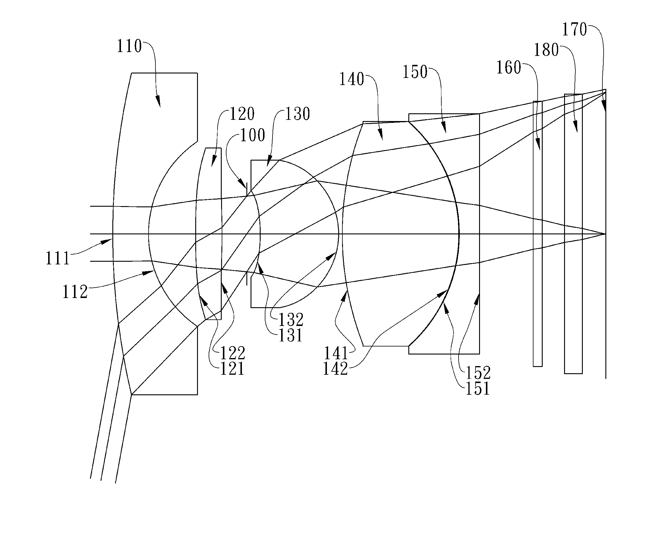
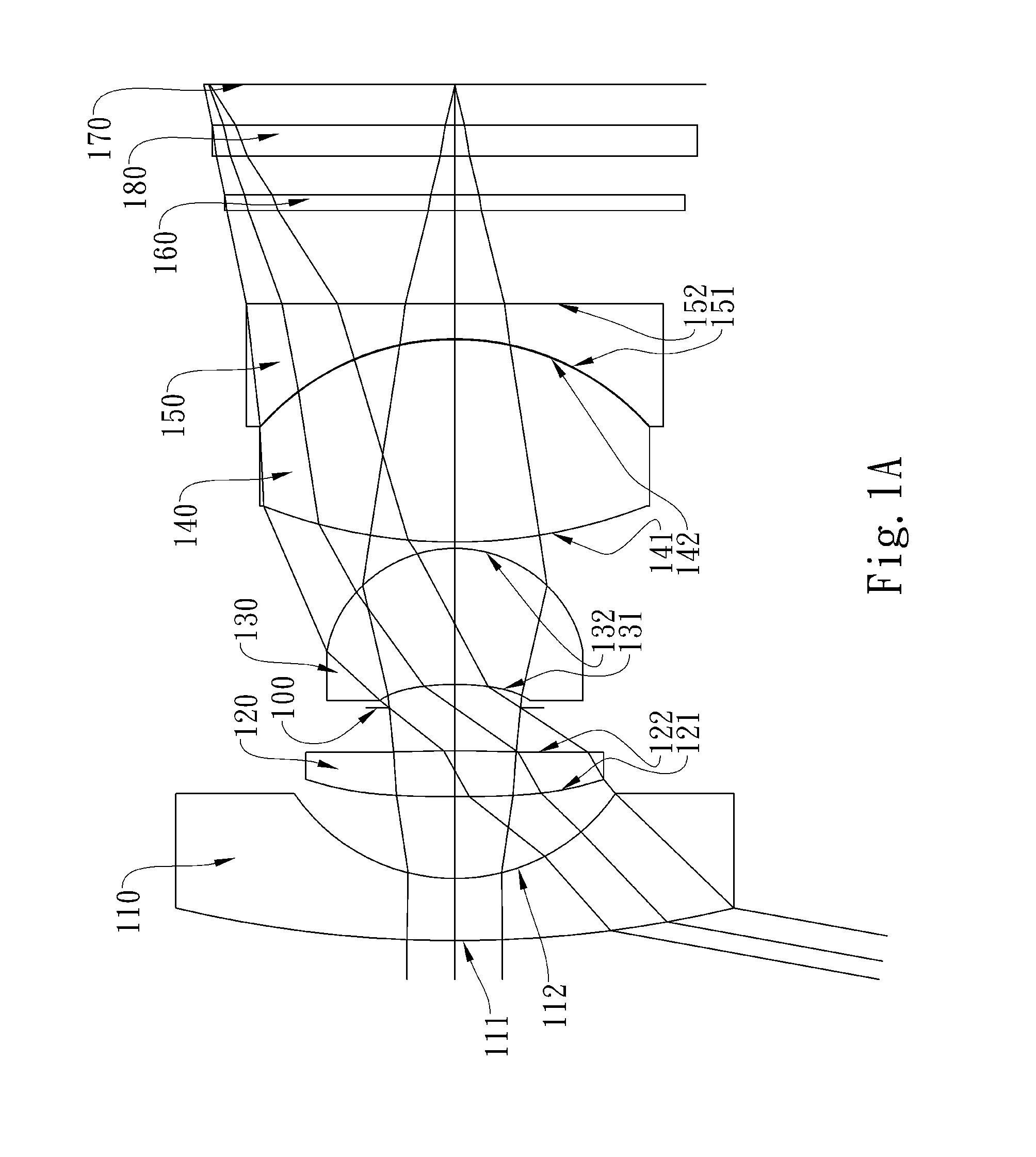
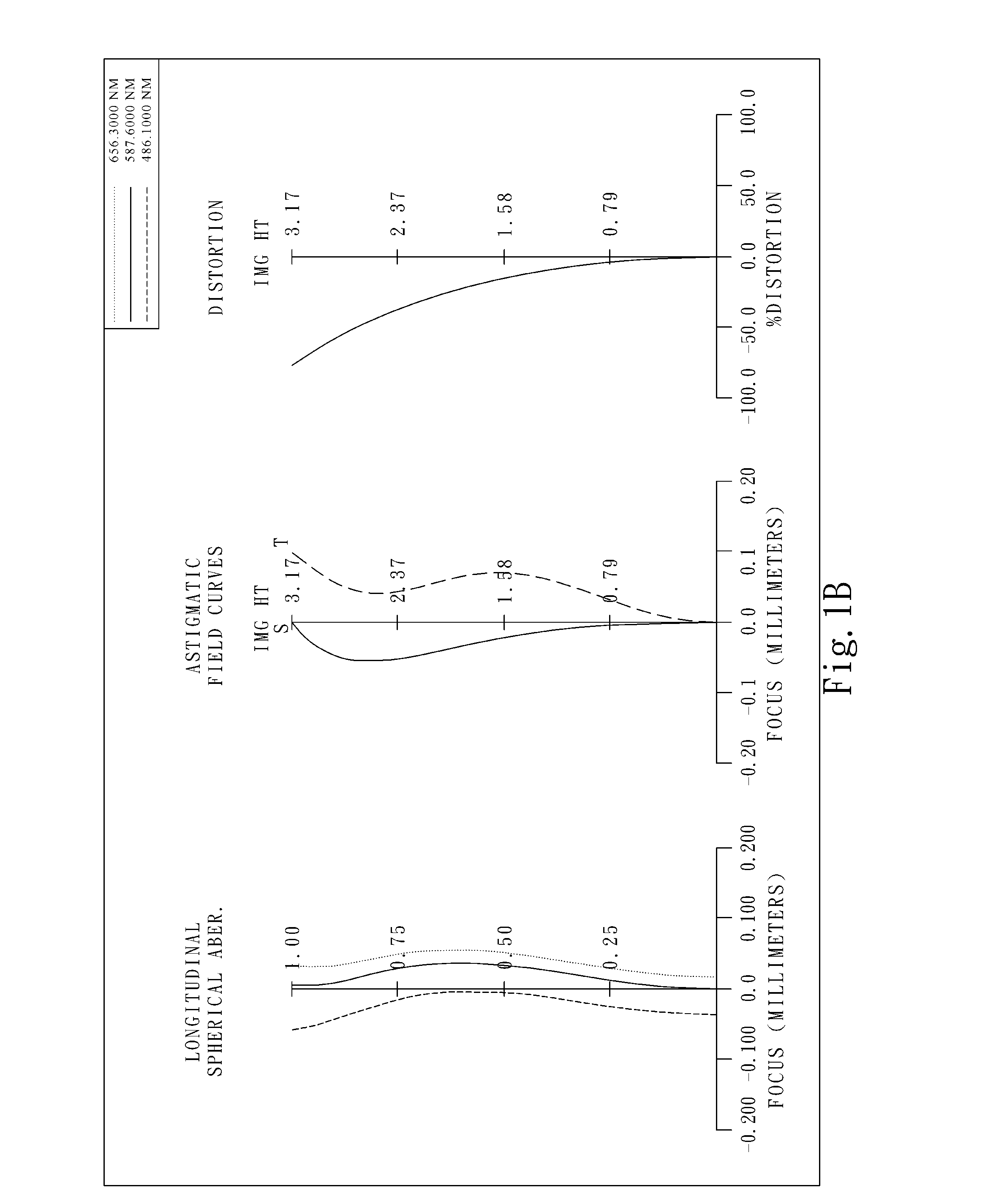
first embodiment
[0070]In the present wide-viewing-angle imaging lens assembly, the focal length of the assembly is f, and it satisfies the relation: f=2.56 (mm).
[0071]In the first embodiment of the present wide-viewing-angle imaging lens assembly, the f-number of the assembly is Fno, and it satisfies the relation: Fno=2.08.
[0072]In the first embodiment of the present wide-viewing-angle imaging lens assembly, half of the maximum field of view of the assembly is HFOV, and it satisfies the relation: HFOV=79.7 (degrees).
[0073]In the first embodiment of the present wide-viewing-angle imaging lens assembly, the Abbe number of the first lens element 110 is V1, the Abbe number of the second lens element 120 is V2, and they satisfy the relation: V1−V2=32.1.
[0074]In the first embodiment of the present wide-viewing-angle imaging lens assembly, the focal length of the assembly is f, the focal length of the first lens element 110 is f1, and they satisfy the relation: f / f1=−0.58.
[0075]In the first embodiment of ...
second embodiment
[0088]In the present wide-viewing-angle imaging lens assembly, the focal length of the assembly is f, and it satisfies the relation: f=2.45 (mm).
[0089]In the second embodiment of the present wide-viewing-angle imaging lens assembly, the f-number of the assembly is Fno, and it satisfies the relation: Fno=2.40.
[0090]In the second embodiment of the present wide-viewing-angle imaging lens assembly, half of the maximum field of view of the assembly is HFOV, and it satisfies the relation: HFOV=80.9 (degrees).
[0091]In the second embodiment of the present wide-viewing-angle imaging lens assembly, the Abbe number of the first lens element 210 is V1, the Abbe number of the second lens element 220 is V2, and they satisfy the relation: V1−V2=34.5.
[0092]In the second embodiment of the present wide-viewing-angle imaging lens assembly, the focal length of the assembly is f, the focal length of the first lens element 210 is f1, and they satisfy the relation: f / f1=−0.61.
[0093]In the second embodimen...
third embodiment
[0106]In the present wide-viewing-angle imaging lens assembly, the focal length of the assembly is f, and it satisfies the relation: f=2.81 (mm).
[0107]In the third embodiment of the present wide-viewing-angle imaging lens assembly, the f-number of the assembly is Fno, and it satisfies the relation: Fno=2.05.
[0108]In the third embodiment of the present wide-viewing-angle imaging lens assembly, half of the maximum field of view of the assembly is HFOV, and it satisfies the relation: HFOV=70.4 (degrees).
[0109]In the third embodiment of the present wide-viewing-angle imaging lens assembly, the Abbe number of the first lens element 310 is V1, the Abbe number of the second lens element 320 is V2, and they satisfy the relation: V1−V2=32.1.
[0110]In the third embodiment of the present wide-viewing-angle imaging lens assembly, the focal length of the assembly is f, the focal length of the first lens element 310 is f1, and they satisfy the relation: f / f1=−0.49.
[0111]In the third embodiment of ...
PUM
 Abstract
Description
Claims
Application Information