Traffic control method and apparatus for wireless communication

Active Publication Date: 2011-12-29
KDDI CORP
View PDF2 Cites 14 Cited by
  • Summary
  • Abstract
  • Description
  • Claims
  • Application Information

AI Technical Summary

Benefits of technology

[0015]An object of the present invention is to provide a traffic control method and apparatus with which a valuable wireless r

Problems solved by technology

There is thus a technical issue that even when the network side congestion is resolved ther

Method used


Image

  • Traffic control method and apparatus for wireless communication
  • Traffic control method and apparatus for wireless communication
  • Traffic control method and apparatus for wireless communication

Examples


first embodiment

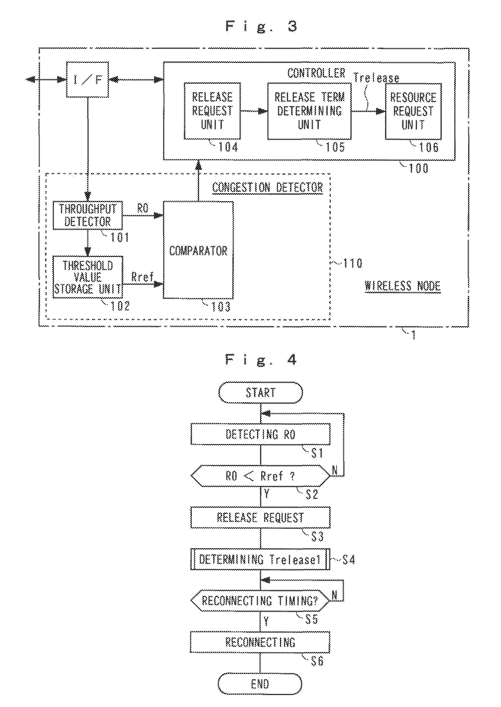
[0046]An operation of the embodiment of the present invention shall now be described in detail with reference to the block diagram together with flowcharts and a time chart. FIG. 4 is a flowchart of operation of the first embodiment and mainly shows a traffic control operation at the wireless node 1. FIG. 5 is a time chart thereof.

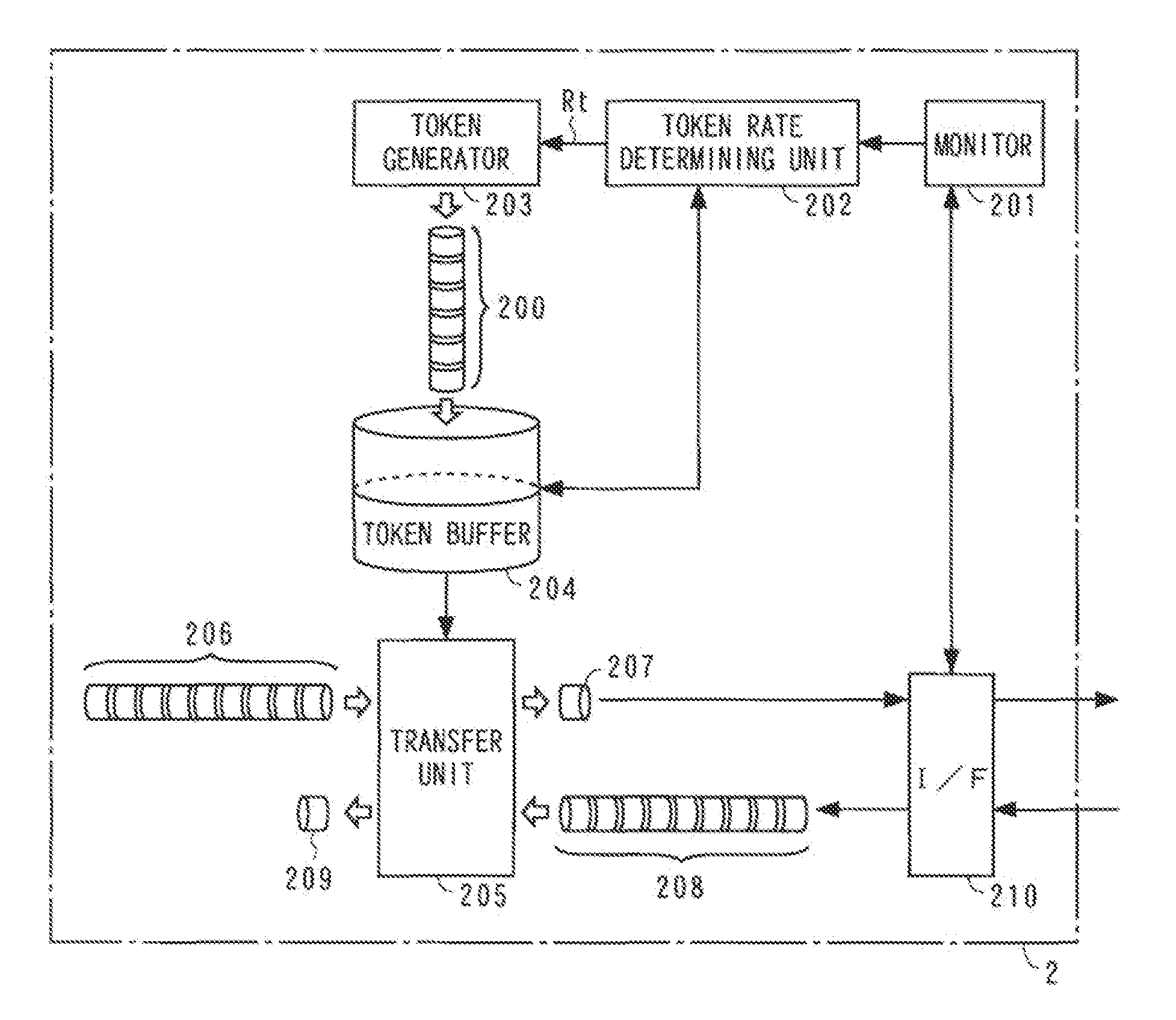
[0047]In step S1, the throughput R0 of the wireless node 1 is detected by the throughput detector 101. The throughput R0 increases and decreases depending on the token rate Rt at the communication modem 2 and thus serves as an index that represents the congestion of the wireless section or the network 4. In step S2, the throughput R0 and the threshold value Rref are compared at the comparator 103. If the throughput R0 falls below the threshold value Rref, as before time t1 in FIG. 5, it is judged that the token rate Rt at the modem 2 is high and a serious congestion is not occurring at the network side and the above process is repeated upon returning to st...

second embodiment

[0059]An operation of a second embodiment that adopts the above dormant mode shall now be described according to each of the options.

[0060]FIG. 7 is a flowchart of an operation unique to the option A, and symbols that are the same as the above express the same or equivalent portions.

[0061]When in step S3, the release request unit 104 requests the release of the wireless resource, the controller 100 detects the release request in step S31 and then step S32. In step S32, just the physical connection of the wireless layer is disconnected while maintaining the logical connection of the data link and above according to the dormant mode.

[0062]In step S4, Trelease1 is determined. In step S5, it is judged whether or not Trelease1 has elapsed since the release of the wireless resource. If it is judged that Trelease1 has elapsed, the resource request unit 106 requests reconnection by resource acquisition in step S6.

[0063]At the controller 100, step S34 is entered when the reconnection request...

third embodiment

[0073]FIG. 10 is a flowchart of operation of a third embodiment, and FIG. 11 is a time chart thereof.

[0074]In step S1, the throughput R0 of the wireless node 1 is detected. In step S2, the throughput R0 and the threshold value Rref are compared.

[0075]If at a time t1 in FIG. 8, R0 falls below Rref, this is detected in step S2. In step S3, the release request unit 104 requests the release of a wireless resource. In response to the request, the controller 100 suppresses the throughput R0 to a restricted rate (shape rate) Rshape that is lower than the current token rate Rt to reduce the session bandwidth in the wireless section. Consequently in the wireless section, a session bandwidth equivalent to the reduced session bandwidth is allocated to other sessions. In step S4a, the release term Trelease (Trelease2 here) of the wireless resource is determined by the release term determining unit 105.

[0076]FIG. 12 is a flowchart of an example of a method for determining Trelease2 in the step S...


PUM


Abstract

A throughput detector 101 detects a throughput R0. A threshold value Rref of the throughput R0 at which a network side can be presumed to be congested is stored in a threshold value storage unit 102. A comparator 103 compares the current throughput R0 with the threshold value Rref. A release request unit 104 requests release of a wireless resource when the throughput R0 falls below the threshold value Rref. In response to the release request, a controller 100 suitably disconnects a physical layer or a logical layer of a wireless section to release the wireless resource. A release term determining unit 105 determines a release term of the wireless resource. A resource request unit 106 makes the released wireless resource be acquired anew after the elapse of the release term to reconnect the wireless communication.

Description

[0001]The present application is claims priority of Japanese Patent Application Serial No. 2010-146382, filed Jun. 28, 2010 and No. 2010-201909, filed Sep. 9, 2010, the content of which are hereby incorporated by reference in its entirety.1. FIELD OF THE INVENTION[0002]The present invention relates to a traffic control method and apparatus favorable for wireless communication in which bandwidth is controlled by a token bucket algorithm.2. DESCRIPTION OF THE RELATED ART[0003]As a method for controlling bandwidth in accordance with a congestion level of a network, Patent Document 1 discloses an art of limiting input and output of a transfer buffer using a token bucket algorithm. The token bucket algorithm is mainly arranged from a token rate and a token buffer. A token is a communication right for a data amount transferred by a communication apparatus. The token rate is a minimum throughput allowed for the communication apparatus. The token buffer is replenished at the token rate with...

Claims


Application Information

Patent Timeline
IPC IPC(8): H04W28/14
CPCH04L47/11H04L47/14H04L47/215H04W76/066H04W28/10H04W72/00H04W76/048H04W28/02H04W76/36H04W76/28H04W8/04
Inventor HIEHATA, YASUHIKOKOTO, HIDEYUKINAKAMURA, HAJIME
Owner KDDI CORP
Why Eureka
Try Eureka